|
Sensor Supply Voltage (4) Circuit – Shorted High
|

Overview
| CODE | REASON | EFFECT |
| Fault Code: 2185 PID: S232 SPN: 620 FMI: 3 LAMP: Amber SRT: |
Sensor Supply Voltage (4) Circuit – Shorted High . High voltage detected on sensor supply voltage (4) circuit. |
Possible reduced performance. |
|
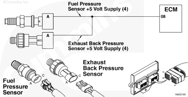
Sensor Supply Voltage (4) Circuit |
 |
;)
;)
Circuit Description
This circuit is the voltage supply for the primary fuel pressure sensor and exhaust back pressure sensor.
Component Location
The sensor supply voltage (4) circuit is contained in the wiring harness.
Shop Talk
The voltage supplies on the B and C Gas Plus engines are broken up into 1, 2, 3, and 4. On the L Gas Plus engine, voltage supplies are broken up into 1, 2, and 4.
Cautions and Warnings
 CAUTION CAUTION To reduce the possibility of damaging a new ECM, all other active fault codes must be investigated prior to replacing the ECM. |
|
CAUTION To reduce the possibility of pin and harness damage, use the following test lead when taking a measurement: |
Troubleshooting Steps
| STEPS | SPECIFICATIONS | |
|---|---|---|
| STEP 1. | Check the fault codes. | |
| STEP 1A. Check for an inactive fault code. | Fault Code 2185 inactive? | |
| STEP 2. | Check the ECM and sensor harness. | |
| STEP 2A. Inspect the ECM and engine harness connector pins. | Dirty or damaged pins? | |
| STEP 2B. Check for a pin to pin short circuit in the engine harness. | Greater than 100k ohms? | |
| STEP 2C. Check for an inactive fault code. | Fault Code 2185 inactive? | |
| STEP 3. | Clear the fault codes. | |
| STEP 3A. Disable the fault code. | Fault Code 2185 inactive? | |
| STEP 3B. Clear the inactive fault codes. | All fault codes cleared? | |
Guided Step 1 – Check the fault codes.
| Guided Step 1A – Check for an inactive fault code. | |
|---|---|
Conditions
Action
|
|
|
Fault Code 2185 inactive? |
|
| YES | NO |
| No Repair | No Repair |
Guided Step 2 – Check the ECM and engine harness.
| Guided Step 2A – Inspect the ECM and engine harness connector pins. | |
|---|---|
Conditions
Action
For general inspection techniques, refer to Component Connector and Pin Inspection, Procedure 019-361. |
|
|
Dirty or damaged pins? |
|
| YES | NO |
|
A defective connection has been detected in the ECM engine connector or engine harness connector. Repair the damaged pins. Repair or replace the engine harness, whichever has the damaged pins. |
No Repair |
| Guided Step 2B – Check for a short circuit from pin to pin. | |
|---|---|
Conditions
Action
Refer to the circuit diagram or wiring harness for connector pin identification. For general resistance techniques, refer to the Resistance Measurements Using a Multimeter and Wiring Diagram, Procedure 019-360. |
|
|
Greater than 100k ohms? |
|
| YES | NO |
| No Repair |
A pin to pin short circuit on the sensor SUPPLY number 4 line has been detected in the engine harness. Repair or replace the engine harness. |
| Guided Step 2C – Check for an inactive fault code. | |
|---|---|
Conditions
Action
|
|
|
Fault Code 2185 inactive? |
|
| YES | NO |
| No Repair |
Replace the ECM. Call for pre-authorization. Refer to Procedure 019-031. |
Guided Step 3 – Clear the fault codes.
| Guided Step 3A – Disable the fault code. | |
|---|---|
Conditions
Action
|
|
|
Fault Code 2185 inactive? |
|
| YES | NO |
| No Repair | No Repair |
| Guided Step 3B – Clear the inactive fault codes. | |
|---|---|
Conditions
Action
|
|
|
All fault codes cleared? |
|
| YES | NO |
| No Repair | No Repair |
|
Repair complete
|
Appropriate troubleshooting steps
|