|
Exhaust Back Pressure – Data Valid but Above Normal Operational Range – Moderately Severe Level
|

Overview
| CODE | REASON | EFFECT |
| Fault Code: 2187 PID: S34 SPN: 648 FMI: 0/16 LAMP: Amber SRT: |
Exhaust Back Pressure – Data Valid but Above Normal Operational Range – Moderately Severe Level. Pressure is above the engine protection limit. |
Progressive speed and power derate. |
|
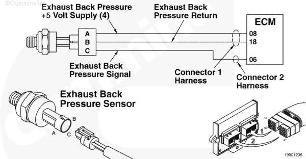
Exhaust Back Pressure Sensor Circuit |
 |
;)
;)
Circuit Description
The electronic control module (ECM) uses this sensor’s input to determine the pressure of the exhaust gas, which affects the fueling of the engine.
Component Location
The exhaust back pressure sensor is located above the rocker housing and is attached to the closed-crankcase ventilation filter bracket.
Shop Talk
The arrangement of this sensor allows some condensation/sludge buildup within the tube arrangement. Before replacing the sensor, make sure this tube is free from blockage.
On the L Gas Plus, an original equipment manufacturer (OEM) tube from the exhaust connects to a boiler box on the exhaust side of the engine. A tube then connects the box to the exhaust back pressure sensor.
Troubleshooting Steps
| STEPS | SPECIFICATIONS | |
|---|---|---|
| STEP 1. | Check the fault codes. | |
| STEP 1A. Read the fault codes. | Fault Code 2187 active? | |
| STEP 2. | Check the exhaust back pressure sensor. | |
| STEP 2A. Inspect the exhaust back pressure sensor and engine harness connector pins. | Dirty or damaged pins? | |
| STEP 2B. Check the sensor accuracy. | Exhaust back pressure (absolute) read atmospheric pressure? | |
| STEP 2C. Inspect the back pressure sensing hardware for cracked fittings, plugging, or leaks. Verify back pressure measurement location. | Hardware failure or installation issue found? | |
| STEP 2D. Check the exhaust back pressure. | Pressure between 61 to 127 mm Hg [2.4 to 5.0 in Hg]? | |
| STEP 3. | Check for excessive oil consumption. | |
| STEP 3A. Inspect the closed crankcase ventilation system. | Excessive oil, plugging, wrong orientation, or oil carryover? | |
| STEP 3B. Check for oil residue in the turbocharger compressor outlet plumbing. | Oil residue present? | |
| STEP 3C. Check for oil in the charge air cooler outlet. | Oil present? | |
| STEP 3D. Check for oil residue in the turbocharger turbine outlet. | Oil residue present? | |
| STEP 3E. Inspect the valve stem seals. | Damaged, cracked, wrong, or improperly installed valve stem seals? | |
| STEP 4. | Check air to fuel ratio control. | |
| STEP 4A. Check the overhead set. | Valve lash out of specification? | |
| STEP 4B. Check the gas flow measurement. | Excessive compressor oil carryover in the fuel system. | |
| STEP 4C. Check the fuel mixer housing. | Fuel mixer incorrect or venturi sleeve not seated properly? |
|
| STEP 4D. Check the gas mass flow sensor and fuel control valve. | Steady-state gas mass flow compensation > 90 percent and gas mass flow deviation > 4.7 lt/hr [10 lb/hr]? | |
| STEP 4E. Check for an exhaust system leak. | Exhaust leaks? | |
| STEP 5. | Check combustion chamber sealing. | |
| STEP 5A. Check cylinder leak down. | Does cylinder pass leak down test? | |
| STEP 6. | Check the exhaust back pressure. | |
| STEP 6A. Check the exhaust back pressure. | Pressure between 61 to 127 mm Hg [2.4 to 5.0 in Hg]? | |
| STEP 7. | Clear the fault codes. | |
| STEP 7A. Disable the fault code. | Fault Code 2187 inactive? | |
| STEP 7B. Clear the inactive fault codes. | All fault codes cleared? | |
Guided Step 1 – Check the fault codes.
| Guided Step 1A – Read the fault codes. | |
|---|---|
Conditions
ActionCheck the fault codes.
|
|
|
Fault Code 2187 active? |
|
| YES | NO |
| No Repair | No Repair |
Guided Step 2 – Check the exhaust back pressure sensor.
| Guided Step 2A – Inspect the exhaust back pressure sensor and engine harness connector pins. | |
|---|---|
Conditions
ActionInspect the sensor and engine harness connector pins for the following:
For general inspection techniques, refer to Component Connector and Pin Inspection, Procedure |
|
|
Dirty or damaged pins? |
|
| YES | NO |
|
Us electronic contact cleaner, Part Number 3824510, to flush the dirt, debris, or moisture from the connector pins. Install the appropriate connector seal if it is damaged or missing. Repair or replace the engine harness. Refer to Procedure Replace the sensor. Refer to Procedure |
No Repair |
| Guided Step 2B – Check the sensor accuracy. | |
|---|---|
Conditions
ActionVerify the sensor accuracy.
Note: Convert psia to in. Hg. by multiplying by 2.036. |
|
|
Exhaust back pressure (absolute) read atmospheric pressure? |
|
| YES | NO |
| No Repair |
Verify the sensing tube is free of blockage and replace the sensor. refer to Procedure |
| Guided Step 2C – Inspect the back pressure sensing hardware for cracked fittings, plugging, or leaks. Verify back pressure measurement location. | |
|---|---|
Conditions
ActionInspect the sensing hardware and measurement location.
|
|
|
Hardware failure or installation issue found? |
|
| YES | NO |
|
Repair or replace the failed components, or correct the exhaust back pressure measurement location. |
No Repair |
| Guided Step 2D – Check the exhaust back pressure. | |
|---|---|
Conditions
ActionCheck the exhaust back pressure.
Refer to Procedure 011-009 in the Troubleshooting and Repair Manual, C Gas, C Gas Plus, and L Gas Plus Engines, Bulletin Make sure the back pressure tube is free from blockage. |
|
|
Pressure between 61 to 127 mm Hg [2.4 to 5.0 in Hg]? |
|
| YES | NO |
| No Repair |
Remove the catalyst and utilize piping to restrict to required back pressure. |
Guided Step 3 – Check for excessive oil consumption.
| Guided Step 3A – Inspect the closed crankcase ventilation system. | |
|---|---|
Conditions
ActionCheck the closed crankcase ventilation system.
|
|
|
Excessive oil, plugging, wrong orientation, or oil carryover? |
|
| YES | NO |
|
Repair the closed crankcase ventilation system. |
No Repair |
| Guided Step 3B – Check for oil residue in the turbocharger compressor outlet plumbing. | |
|---|---|
Conditions
ActionCheck for oil residue.
|
|
|
Oil residue present? |
|
| YES | NO |
|
The turbocharger is the source of the oil. Replace the turbocharger. Refer to Procedure 010-033 in the Troubleshooting and Repair Manual, C Gas, C Gas Plus, and L Gas Plus Engines, Bulletin |
No Repair |
| Guided Step 3C – Check for oil in the charge air cooler outlet. | |
|---|---|
Conditions
ActionCheck the charge air cooler.
|
|
|
Oil present? |
|
| YES | NO |
|
Clean the charge air cooler. Remove and clean the intake piping. Refer to Procedure 010-027 in the Troubleshooting and Repair Manual, C Gas, C Gas Plus, and L Gas Plus Engines, Bulletin |
No Repair |
| Guided Step 3D – Check for oil residue in the turbocharger turbine outlet. | |
|---|---|
Conditions
ActionCheck the turbocharger turbine outlet.
|
|
|
Oil residue present? |
|
| YES | NO |
|
The turbocharger is the source of the oil. Replace the turbocharger. Refer to Procedure 010-033 in the Troubleshooting and Repair Manual, C Gas, C Gas Plus, and L Gas Plus Engines, Bulletin Replace the oxygen sensor. Refer to Procedure Clean the exhaust system of any oil or residue. |
No Repair |
| Guided Step 3E – Inspect the valve stem seals. | |
|---|---|
Conditions
ActionRemove the valve covers.
|
|
|
Damaged, cracked, wrong, or improperly installed valve stem seals? |
|
| YES | NO |
|
Replace the valve stem seals. Clean the exhaust system of any oil or residue. Refer to the Troubleshooting and Repair Manual, C Gas, C Gas Plus, and L Gas Plus Engines, Bulletin |
No Repair |
Guided Step 4 – Check air to fuel ratio control.
| Guided Step 4A – Check the overhead set. | |
|---|---|
Conditions
|
|
|
Valve lash out of specification? |
|
| YES | NO |
|
Adjust the overhead. Refer to Procedure 003-004 in the Troubleshooting and Repair Manual, C Gas, C Gas Plus, and L Gas Plus Engines, Bulletin |
No Repair |
| Guided Step 4B – Check the gas flow measurement. | |
|---|---|
Conditions
ActionCheck the gas flow measurement.
|
|
|
Excessive compressor oil carryover in the fuel system? |
|
| YES | NO |
|
Replace the fuel system screen pack and the gas mass flow sensor. Refer to Procedure Clean the fuel system of compressor oil contamination. Be sure the fuel filter drain interval is in accordance with the maintenance schedule. |
No Repair |
| Guided Step 4C – Check the fuel mixer housing. | |
|---|---|
Conditions
ActionVerify that the fuel shutoff valve (or plug on B LPG Plus) is installed properly and check for debris on the screen. B Gas Plus and B LPG Plus:
C Gas Plus and L Gas Plus
|
|
|
Fuel mixer incorrect or venturi sleeve |
|
| YES | NO |
|
Replace or repair the fuel mixer. Refer to the Troubleshooting and Repair Manual, C Gas, C Gas Plus, and L Gas Plus Engines, Bulletin |
No Repair |
| Guided Step 4D – Check the gas mass flow sensor and fuel control valve. | |
|---|---|
Conditions
ActionCheck the gas mass flow sensor and fuel control valve. Automatic Transmission:
Manual Transmission:
Check for the following:
|
|
|
Steady-state gas mass flow compensation > 90 percent and gas mass flow deviation > 4.7 lt/hr [10 lb/hr]? |
|
| YES | NO |
|
Be sure voltage regulation is installed as appropriate. Replace the gas mass flow sensor or replace the fuel control valve. Refer to Procedure |
No Repair |
| Guided Step 4E – Check for an exhaust system leak. | |
|---|---|
Conditions
ActionCheck for exhaust leaks.
|
|
|
Exhaust leaks? |
|
| YES | NO |
|
Repair or replace the leaking components. Refer to the Troubleshooting and Repair Manual, C Gas, C Gas Plus, and L Gas Plus Engines, Bulletin |
No Repair |
Guided Step 5 – Check combustion chamber sealing.
| Guided Step 5A – Check cylinder leak down. | |
|---|---|
Conditions
|
|
|
Does cylinder pass leak down test? |
|
| YES | NO |
| No Repair |
Repair the engine as necessary. Refer to the Troubleshooting and Repair Manual, C Gas, C Gas Plus, and L Gas Plus Engines, Bulletin |
Guided Step 6 – Check the exhaust back pressure.
| Guided Step 6A – Check the exhaust back pressure. | |
|---|---|
Conditions
ActionCheck the exhaust back pressure.
|
|
|
Pressure between 61 to 127 mm Hg [2.4 to 5.0 in Hg]? |
|
| YES | NO |
| No Repair |
Inspect the oxidation catalyst and/or muffler, and replace according to the manufacturer’s instructions. |
Guided Step 7 – Clear the fault codes.
| Guided Step 7A – Disable the fault code. | |
|---|---|
Conditions
ActionDisable the fault code.
|
|
|
Fault Code 2187 inactive? |
|
| YES | NO |
| No Repair |
Return to the troubleshooting steps or contact a Cummins Authorized Repair Location if all steps have been completed and checked again. |
| Guided Step 7B – Clear the inactive fault codes. | |
|---|---|
Conditions
ActionClear the inactive fault codes.
|
|
|
All fault codes cleared? |
|
| YES | NO |
| No Repair |
Troubleshoot any remaining active fault codes. |
|
Repair complete
|
Appropriate troubleshooting charts
|