View Related Topic
Preparatory Steps
TOC
Disconnect the injection pump supply line. Refer to Procedure006-024 .
Remove the injector supply lines. Refer to Procedure006-051 .
Disconnect the fuel drain line. Refer to Procedure006-013 .
Disconnect the pumping control valve 4-pin Deutsch connector.
Disconnect the injection control valve 4-pin Deutsch connector.
Disconnect the accumulator pressure sensor.
Disconnect the accumulator temperature sensor.
Remove
TOC
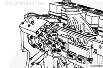
Remove the injection pump upper support bracket.
Remove the injection pump tail support bracket.
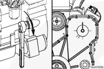
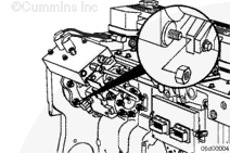
Locate top dead center for cylinder number 1 by barring the engine slowly until the line on the pump gear lines up with the line on the gear cover.
Remove the fuel pump drive gear retaining nut and washer.
Remove the four mounting nuts.
Remove the fuel injection pump.
Clean and Inspect for Reuse
TOC
The fuel pump driveshaft keymust not be sheared.
If the key is sheared, the cam housing module of the fuel pumpmust be replaced and the drive gearmust be replaced.
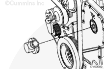
Check that the locating dowel is installed in the cam housing.
Install
TOC
Be sure the engine is at number 1 cylinder top dead center. The fuel pump gear timing mark should align with the top dead center mark on the gear housing.
Clean the fuel injection pump drive shaft with an evaporative cleaner.
Clean the fuel pump gear inside diameter with an evaporative cleaner.
The fuel pump drive gear inside diameter and the drive shaft outside diametermust be clean and dry before installing the gear.
Make sure the fuel injection pump is at its top dead center position.
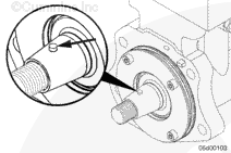
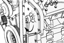
The fuel injection pump is at number 1 cylinder top dead center when the dowel pin in the shaft (A) is perpendicular to the top of the accumulator.
Be sure that the dowel is installed in the pump driveshaft.
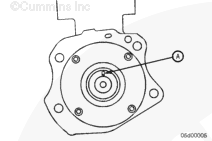
Make sure the o-ring seals for the oil feed orifice (A) and pilot (B) are correctly installed and arenot damaged.
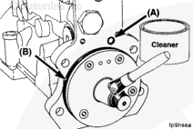
Lubricate the mounting flange with cleaner.
The fuel pump drive gear inside diameter and the shaft outside diametermust be clean and dry before installing the gear.
Slide the fuel injector pump shaft through the drive gear and position the fuel injection pump flange onto the mounting studs.
Make sure the dowel pin in the shaft (A) lines up with the keyway in the fuel injection pump gear.
Make sure the dowel pin in the fuel injection pump flange lines up with the hole in the gear housing.
Install the mounting nuts.
Install the fuel injection pump upper support bracket.
Install the fuel injection pump tail support bracket.
Fuel Pump Mounting Nuts
44 n.m
[32 ft-lb]
Fuel Pump Upper Support Brackets (8.8 or 9.8 bracket capscrews)
44 n.m
[32 ft-lb]
Fuel Pump Tail Support Bracket (10.9 capscrews)
65 n.m
[48 ft-lb]
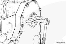
Tighten the fuel injection pump drive gear nut.
Torque Value: 180 n.m [132 ft-lb]
Finishing Steps
TOC
Install the gear cover access cap hand tight.
Connect the injection pump supply line. Refer to Procedure006-024 .
Connect the injector supply lines. Refer to Procedure006-051 .
Connect the fuel drain line. Refer to Procedure006-013 .
Connect the pumping control valve 4-pin Deutsch connector.
Connect the injection control valve 4-pin Deutsch connector.
Connect the accumulator pressure sensor to the engine harness.
Connect the accumulator temperature sensor to the engine harness.
Operate the engine and check for leaks.
Last Modified: 10-Oct-2006
Published by Jack
Hello, I'm Jack, a diesel engine fan and a blogger. I write about how to fix and improve diesel engines, from cars to trucks to generators. I also review the newest models and innovations in the diesel market. If you are interested in learning more about diesel engines, check out my blog and leave your feedback.
View all posts by Jack


;)
;)
;)
;)
;)
;)
;)
;)
;)
;)
;)
;)
;)
;)
;)
;)
;)
;)
;)
;)