|
Oil Pressure Sensor Circuit
|

Overview
| CODE | REASON | EFFECT |
| Fault Code: 141 PID: P100 SPN: 100 FMI: 4 LAMP: Yellow SRT: 00-087 |
Low voltage detected at oil pressure sensor signal pin 7 of the sensor harness connector. |
No engine protection for oil pressure. |
|
Oil Pressure Sensor Circuit |
 |
Circuit Description
The oil pressure sensor is used by the electronic control module (ECM) to monitor the lubricating oil pressure. The ECM monitors the voltage on the signal pin and converts this to a pressure value.
Component Location
- M11 – The oil pressure sensor is located on the engine block to the right of the ECM.
- 1994 N14 – The oil pressure sensor is located on the engine block near the pan rail on the fuel pump side of the engine.
- 1991 N14 – The oil pressure sensor is located on the engine block above the fuel supply pump.
Shop Talk
If Fault Code 143 or 415 is not present, the problem is not base engine related.
Cautions and Warnings
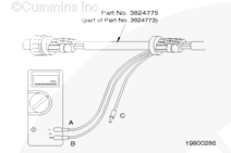
 CAUTION CAUTION To reduce the possibility of pin and harness damage, use the following test leads when taking a measurement: |
|
CAUTION To reduce the possibility of damaging the new ECM, all other active fault codes must be investigated prior to replacing the ECM. |
|
CAUTION To reduce the possibility of pin and harness damage, use this test lead when taking a measurement: |
|
CAUTION To reduce the possibility of damaging a new ECM, all other active fault codes must be investigated prior to replacing the ECM. |
|
CAUTION To reduce the possibility of pin and harness damage, use the following test lead when taking a measurement: |
|
CAUTION To reduce the possibility of pin and harness damage, use this test lead when taking a measurement: |
|
CAUTION To reduce the possibility of pin and harness damage, use the following test lead when taking a measurement: |
|
CAUTION To reduce the possibility of pin and harness damage, use the following test lead when taking a measurement: |
|
CAUTION To reduce the possibility of pin and harness damage, use the following test lead when taking a measurement: |
Troubleshooting Steps
| STEPS | SPECIFICATIONS | |
|---|---|---|
| STEP 1. | Check for multiple fault codes. | |
| STEP 1A. Read the fault codes. | Fault Codes 123, 145, 154, 213, 222, 352, and 422 are not active | |
| STEP 2. | Check the oil pressure sensor. | |
| STEP 2A. Inspect the oil pressure sensor and the sensor harness connector pins. | No damaged pins | |
| STEP 2B. Read the fault codes. | Fault Code 141 active | |
| STEP 2C. Check the oil pressure sensor supply voltage. | 4.75 to 5.25 VDC | |
| STEP 2C-1. Check the oil pressure sensor supply voltage. | ||
| STEP 2C-2. Measure the voltage out of the ECM. | ||
| STEP 2D. Check the oil pressure sensor signal voltage. | 0.40 to 0.60 VDC | |
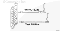
| STEP 2D-1. Check for a short circuit from pin to pin. | ||
| STEP 2D-2. Check for continuity in the sensor harness. | ||
| STEP 2D-3. Check ECM response. | ||
| STEP 2D-4. Check ECM signal pin to return pin resistance. | ||
| STEP 3. | Check the sensor harness. | |
| STEP 3A. Inspect the sensor harness and the ECM connector for damaged pins. | No damaged pins | |
| STEP 3B. Read the fault codes. | Fault Code 141 active | |
| STEP 3C. Check for a short circuit to ground. | More than 100k ohms | |
| STEP 3D. Check for a short circuit from pin to pin. | More than 100k ohms | |
| STEP 3E. Check for correct pin-to-pin wiring between sensor and ECM and for continuity between sensor and ECM. | Less than 10 ohms | |
| STEP 3F. Clear and check the fault codes. | No reoccurrence of Fault Code 141 | |
| STEP 4. | Check for an ECM response. | |
| STEP 4A. Check for the appropriate ECM response. | Fault Code 141 inactive, Fault Code 135 active | |
| STEP 4B. Check ECM signal pin resistance. | Replace the ECM | |
| STEP 5. | Clear the fault codes. | |
| STEP 5A. Disable the fault code. | Fault Code 141 inactive | |
| STEP 5B. Clear the inactive fault codes. | All fault codes cleared | |
Guided Step 1 – Check for multiple fault codes.
| Guided Step 1A – Read the fault codes. | |
|---|---|
Conditions
Action
|
|
| OK | NOT OK |
|
Fault Codes 123, 145, 154, 213, 222, 352, and 422 are not active |
Possible sensor failure, a short circuit to ground in the sensor positive (+) 5 VDC common supply, or a short circuit from pin to pin. |
|
Fault Code Multiple A
|
|
Guided Step 2 – Check the oil pressure sensor.
| Guided Step 2A – Inspect the oil pressure sensor and the sensor harness connector pins. | |
|---|---|
Conditions
Action
|
|
| OK | NOT OK |
|
No damaged pins |
Repair the damaged pins.
|
| Guided Step 2B – Read the fault codes. | |
|---|---|
Conditions
Action
|
|
| OK | NOT OK |
|
Fault Code 141 active |
Repair complete. |
|
CAUTION To reduce the possibility of pin and harness damage, use this test lead when taking a measurement: |
|
CAUTION To reduce the possibility of pin and harness damage, use this test lead when taking a measurement: |
|
CAUTION To reduce the possibility of damaging a new ECM, all other active fault codes must be investigated prior to replacing the ECM. |
|
CAUTION To reduce the possibility of pin and harness damage, use the following test lead when taking a measurement: |
| Guided Step 2C – Check the oil pressure sensor supply voltage. | ||
|---|---|---|
Conditions
Action
|
|
|
| OK | NOT OK | |
|
4.75 to 5.25 VDC |
Does not meet specifications. |
|
|
CAUTION To reduce the possibility of pin and harness damage, use this test lead when taking a measurement: |
| Guided Step 2C-1 – Check the oil pressure sensor supply voltage. | ||
|---|---|---|
Conditions
Action
Note: Do not connect the sensor to the breakout cable.
|
|
|
| OK | NOT OK | |
|
4.75 to 5.25 VDC
|
Does not meet specifications. |
|

|
CAUTION To reduce the possibility of damaging a new ECM, all other active fault codes must be investigated prior to replacing the ECM. |
|
CAUTION To reduce the possibility of pin and harness damage, use the following test lead when taking a measurement: |
| Guided Step 2C-2 – Measure the voltage out of the ECM. | ||
|---|---|---|
Conditions
Action
|
|
|
| OK | NOT OK | |
|
4.75 to 5.25 VDC |
Replace the ECM. Refer to Procedure 019-031. |
|
|
CAUTION To reduce the possibility of pin and harness damage, use this test lead when taking a measurement: |
|
CAUTION To reduce the possibility of pin and harness damage, use this test lead when taking a measurement: |
|
CAUTION To reduce the possibility of pin and harness damage, use this test lead when taking a measurement: |
|
CAUTION To reduce the possibility of pin and harness damage, use the following test lead when taking a measurement: |
|
CAUTION To reduce the possibility of pin and harness damage, use the following test lead when taking a measurement: |
| Guided Step 2D – Check the oil pressure sensor signal voltage. | ||
|---|---|---|
Conditions
Action
|
|
|
| OK | NOT OK | |
|
0.40 to 0.60 VDC |
Does not meet specifications. |
|
|
CAUTION To reduce the possibility of pin and harness damage, use this test lead when taking a measurement: |
| Guided Step 2D-1 – Check for a short from pin to pin. | |
|---|---|
Conditions
Action
|
|
| OK | NOT OK |
|
More than 100k ohms |
Repair or replace the sensor harness. |
|
CAUTION To reduce the possibility of pin and harness damage, use this test lead when taking a measurement: |
| Guided Step 2D-2 – Check for continuity in the sensor harness. | |
|---|---|
Conditions
Action
|
|
| OK | NOT OK |
|
Less than 10 ohms |
Correct pin-to-pin wiring or open circuit. |
|
CAUTION To reduce the possibility of pin and harness damage, use the following test lead when taking a measurement: |
| Guided Step 2D-3 – Check ECM response. | ||
|---|---|---|
Conditions
Action
|
|
|
| OK | NOT OK | |
|
Fault Code 141 inactive, Fault Code 135 active |
Fault Code 141 active
|
|
|
CAUTION To reduce the possibility of pin and harness damage, use the following test lead when taking a measurement: |
| Guided Step 2D-4 – Check ECM signal pin to return pin resistance. | |
|---|---|
Conditions
Action
|
|
| OK | NOT OK |
|
Less than 100k ohms
|
More than 100k ohms
|
Guided Step 3 – Check the sensor harness.
|
CAUTION To reduce the possibility of damaging the new ECM, all other active fault codes must be investigated prior to replacing the ECM. |
| Guided Step 3A – Inspect the sensor harness and the ECM connector for damaged pins. | |
|---|---|
Conditions
Action
|
|
| OK | NOT OK |
|
No damaged pins |
Repair the damaged pins.
|
| Guided Step 3B – Read the fault codes. | |
|---|---|
Conditions
Action
|
|
| OK | NOT OK |
|
Fault Code 141 active |
Repair complete. |
|
CAUTION To reduce the possibility of pin and harness damage, use the following test lead when taking a measurement: |
| Guided Step 3C – Check for a short circuit to ground. | ||
|---|---|---|
Conditions
Action
|
|
|
| OK | NOT OK | |
|
More than 100k ohms |
Repair or replace the sensor harness. |
|

|
CAUTION To reduce the possibility of pin and harness damage, use the following test lead when taking a measurement: |
| Guided Step 3D – Check for a short circuit from pin to pin. | ||
|---|---|---|
Conditions
Action
|
|
|
| OK | NOT OK | |
|
More than 100k ohms |
Repair or replace the sensor harness. |
|
;)
;)
;)
;)
;)
;)
;)
;)
;)
;)
;)
;)
;)
;)
;)
;)
|
CAUTION To reduce the possibility of pin and harness damage, use the following test lead when taking a measurement: |
| Guided Step 3E – Check for correct pin-to-pin wiring between sensor and ECM and for continuity between sensor and ECM. | |
|---|---|
Conditions
Action
|
|
| OK | NOT OK |
|
Less than 10 ohms |
Repair or replace sensor harness. |
| Guided Step 3F – Clear and check the fault codes. | |
|---|---|
Conditions
Action
|
|
| OK | NOT OK |
|
Fault Code 141 inactive |
Fault Code 141 active |
Guided Step 4 – Check for an ECM response.
|
CAUTION To reduce the possibility of pin and harness damage, use the following test lead when taking a measurement: |
|
CAUTION To reduce the possibility of damaging a new ECM, all other active fault codes must be investigated prior to replacing the ECM. |
| Guided Step 4A – Check for the appropriate ECM response. | ||
|---|---|---|
Conditions
Action
|
|
|
| OK | NOT OK | |
|
Fault Code 141 inactive, Fault Code 135 active |
Replace the ECM. Refer to Procedure 019-031. |
|
|
CAUTION To reduce the possibility of pin and harness damage, use the following test lead when taking a measurement: |
| Guided Step 4B – Check ECM signal pin resistance. | |
|---|---|
Conditions
Action
|
|
| OK | NOT OK |
|
Less than 100k ohms |
Replace the ECM. Refer to Procedure 019-031. |
Guided Step 5 – Clear the fault codes.
| Guided Step 5A – Disable the fault code. | |
|---|---|
Conditions
Action
|
|
| OK | NOT OK |
|
Fault Code 141 inactive |
Return to the troubleshooting steps or contact your nearest Cummins Authorized Repair Location if all the steps have been completed and checked again. |
| Guided Step 5B – Clear the inactive fault codes. | |
|---|---|
Conditions
Action
|
|
| OK | NOT OK |
|
All fault codes cleared |
Troubleshoot any remaining active fault codes. |
|
Repair complete
|
Appropriate troubleshooting charts
|