M11 Series – Service Manual – 001-054   Piston and Connecting Rod Assembly

Preparatory Steps

TOC

 WARNING 

Some state and federal agencies have determined that used engine oil can be carcinogenic and cause reproductive toxicity. Avoid inhalation of vapors, ingestion, and prolonged contact with used engine oil. If not reused, dispose of in accordance with local environmental regulations.
 WARNING 

To reduce the possibility of personal injury, avoid direct contact of hot oil with your skin.

Drain the lubricating oil. Refer to Procedure 007-025 in Troubleshooting and Repair Manual, ISM and QSM11 Engines, Bulletin 3666322 for ISM and QSM11 engines, or Procedure 007-025 in Troubleshooting and Repair Manual, M11 STC, CELECT™, and CELECT™ Plus Engines, Bulletin 3666139 for M11 engines, or Procedure 007-025 in Troubleshooting and Repair Manual, L10G Natural Gas Base Engine, Bulletin 3666207.

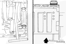
Remove the lubricating oil pan. Refer to Procedure 007-025 in Troubleshooting and Repair Manual, ISM and QSM11 Engines, Bulletin 3666322 for ISM and QSM11 engines, or Procedure 007-025 in Troubleshooting and Repair Manual, M11 STC, CELECT™, and CELECT™ Plus Engines, Bulletin 3666139 for M11 engines, or Procedure 007-025 in Troubleshooting and Repair Manual, L10G Natural Gas Base Engine, Bulletin 3666207.

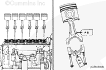
Remove the cylinder head. Refer to Procedure 002-004 in Troubleshooting and Repair Manual, ISM and QSM11 Engines, Bulletin 3666322 for ISM and QSM11 engines, or Procedure 002-004 in Troubleshooting and Repair Manual, M11 STC, CELECT™, and CELECT™ Plus Engines, Bulletin 3666139 for M11 engines, or Procedure 002-004 in Troubleshooting and Repair Manual, L10G Natural Gas Base Engine, Bulletin 3666207.

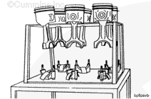
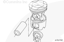
Remove the piston cooling nozzles. Refer to Procedure 001-046 in Troubleshooting and Repair Manual, ISM and QSM11 Engines, Bulletin 3666322 for ISM and QSM11 engines, or Procedure 001-046 in Troubleshooting and Repair Manual, M11 STC, CELECT™, and CELECT™ Plus Engines, Bulletin 3666139 for M11 engines, or Procedure 001-046 in Troubleshooting and Repair Manual, L10G Natural Gas Base Engine, Bulletin 3666207.

 
SMALL | MEDIUM | LARGE

Remove

TOC

 CAUTION 

Do not use emery cloth or sandpaper to remove carbon from the cylinder liners. Aluminum oxide or silicon particles from emery cloth or sandpaper can cause serious engine damage. Do not use any abrasives in the ring travel area. The cylinder liner can be damaged.

Use a fine fibrous abrasive pad such as Scotch-Brite™ 7448, Part Number 3823258, or equivalent, and solvent to remove the carbon.

SMALL | MEDIUM | LARGE


Rotate the crankshaft to position the rod caps at bottom dead center for removal.

Loosen the connecting rod capscrews.

NOTE: Do not remove the capscrews from the rods at this time.

Use a rubber hammer to hit the connecting rod capscrews to loosen the caps from the dowel rings.

SMALL | MEDIUM | LARGE


Remove the connecting rod capscrews.

Remove the rod caps.

Remove the lower rod bearings.

Mark the cylinder number and the letter “L” (lower) in the flat surface of the bearing tangs.

NOTE: Some M Series engines were built without drilled connecting rods and without bearings with an oil hole in the upper bearing shell. Beginning in the fall of 1995, all M series engines are built with drilled connecting rods and bearings with an oil hole in the upper bearing shell.

SMALL | MEDIUM | LARGE


Install two connecting rod guide pins, Part Number 3376038.

Use a “t-handle” piston pusher to push the rod away from the crankshaft.

Push the rod until the piston rings are outside of the top of the cylinder liner.

SMALL | MEDIUM | LARGE


Use both hands to remove the piston and connecting rod assembly.

If parts are reused, the piston and connecting rod assemblies must be installed in the same cylinder number from which they were removed, to make sure of proper fit of worn mating surfaces,

Mark and attach a tag showing the cylinder number from which the piston and connecting rod assembly was removed.

SMALL | MEDIUM | LARGE


Place the rod and piston assemblies in a container to protect them from damage.

 
SMALL | MEDIUM | LARGE


A unique number (not cylinder number) is stamped on the connecting rod and matching cap. When the rods and caps are installed in the engine, the numbers on the rods and caps must match and be installed on the same side of the engine.

SMALL | MEDIUM | LARGE


Remove the upper rod bearing.

Mark the cylinder number and the letter “U” (upper) in the flat surface of the bearing tang.

SMALL | MEDIUM | LARGE
   

Disassemble

TOC

Articulated Piston


Use piston ring expander, Part Number ST-821, to remove the piston rings.

Place a tag on the rings, and record the cylinder number of the piston on the tag.

NOTE: Refer to Procedure 001-047 in Troubleshooting and Repair Manual, ISM and QSM11 Engines, Bulletin 3666322 for piston ring inspection on ISM and QSM11 engines, or Procedure 001-047 in Troubleshooting and Repair Manual, M11 STC, CELECT™, and CELECT™ Plus Engines, Bulletin 3666139 for piston ring inspection on M11 engines, or Procedure 001-047 for piston ring inspection in Troubleshooting and Repair Manual, L10G Natural Gas Base Engine, Bulletin 3666207.

SMALL | MEDIUM | LARGE


Use internal snap ring pliers to remove the snap rings from both sides of the piston.

SMALL | MEDIUM | LARGE


 CAUTION 

Do not use a hammer to remove the piston pins. The piston can distort, causing it to seize in the liner.

If the piston pin can not be easily removed by hand:

  • Install the piston and rod assembly in a container of water.
  • Heat the piston in boiling water for 15 minutes.
  • Use a blunt tool to push the piston pin from the piston and rod assembly.

SMALL | MEDIUM | LARGE


NOTE: When the piston pin is removed from an articulated piston, the skirt will separate from the crown. Use care to reduce the possibility of damage to the piston.

Mark the cylinder number the piston, crown, skirt, and pin was removed from on the parts to make sure they are installed in the correct cylinder if they are used again.

SMALL | MEDIUM | LARGE
   

Clean and Inspect for Reuse

TOC

Articulated Piston


 WARNING 

When using solvents, acids, or alkaline materials for cleaning, follow the manufacturer’s recommendations for use. Wear goggles and protective clothing to reduce the possibility of personal injury.
 WARNING 

Some solvents are flammable and toxic. Read the manufacturer’s instructions before using.
 CAUTION 

Be sure the cleaning solvent is approved for aluminum. Damage to the pistons can result if the wrong solution is used.

Allow the pistons to soak for a minimum of 30 minutes in a tank containing an approved cleaning solvent for aluminum.

Use a hot, soapy solution and a nonmetallic brush to remove carbon deposits.

SMALL | MEDIUM | LARGE


 CAUTION 

Do not use a metal brush. A metal brush will damage the piston ring grooves. Do not use glass beads to clean the grooves. Walnut shell or plastic bead, Part Number 3822735, blasting can be used on ring grooves on the dome or crown of the piston. Use the minimum effective pressure, and do not concentrate the spray in one area for an extended period of time. The recommended blast pressure for plastic bead blasting is 276 kPa [40 psi]. Do not use glass beads or walnut shell blasting on the aluminum piston pin bores or articulated piston skirts. This can cause piston pin bore damage.

SMALL | MEDIUM | LARGE


 WARNING 

When using a steam cleaner, wear safety glasses or a face shield, as well as protective clothing, Hot steam can cause serious personal injury.
 WARNING 

Wear appropriate eye and face protection when using compressed air. Flying debris and dirt can cause personal injury.

Use steam to clean the pistons.

Dry with compressed air.

SMALL | MEDIUM | LARGE


 WARNING 

When using a steam cleaner, wear safety glasses or a face shield, as well as protective clothing, Hot steam can cause serious personal injury.
 WARNING 

When using solvents, acids, or alkaline materials for cleaning, follow the manufacturer’s recommendations for use. Wear goggles and protective clothing to reduce the possibility of personal injury.
 WARNING 

Some solvents are flammable and toxic. Read the manufacturer’s instructions before using.
 WARNING 

Wear appropriate eye and face protection when using compressed air. Flying debris and dirt can cause personal injury.

Use steam or solvent to clean the connecting rods. Dry with compressed air.

SMALL | MEDIUM | LARGE


Refer to Procedure 001-043 for inspection specifications for M series pistons. Refer to Procedure 001-043 for inspection specifications for L10G series pistons in Troubleshooting and Repair Manual, L10G Natural Gas Base Engine, Bulletin 3666207.

SMALL | MEDIUM | LARGE


Refer to Procedure 001-014 in Troubleshooting and Repair Manual, ISM and QSM11 Engines, Bulletin 3666322 for inspection specifications for ISM/QSM11 series connecting rods, or Procedure 001-014 in Troubleshooting and Repair Manual, M11 STC, CELECT™ and CELECT™
Plus engines, Bulletin 3666139 for inspection specifications for M series engines, or Procedure 001-014 in Troubleshooting and Repair Manual, L10G Natural Gas Base Engine, Bulletin 3666207 for inspection specifications for L10G engines.

SMALL | MEDIUM | LARGE
   

Assemble

TOC

Articulated Piston


 CAUTION 

The retainer snap ring must be seated completely in the piston pin groove to reduce the possibility of engine damage during engine operation.

Install a new snap ring in one piston pin bore of each piston skirt.

NOTE: If the pistons are being reused, the crown, skirt, and pin must be matched as they were when they were removed.

SMALL | MEDIUM | LARGE


NOTE: All pistons (bushed and nonbushed) must be properly lubricated prior to assembly.

For all pistons, use a clean, lint free cloth to apply a heavy film of 80W-140 gear oil with EP additive to the following locations:

  • Piston pin bore inside diameter in the piston crown
  • Piston pin bore inside diameter in the piston skirt
  • Rod bushing inside diameter
  • Piston pin

Assemble the piston crown into the piston skirt.

NOTE: It is not necessary to heat the articulated pistons before assembly. The piston pin is slip fitted.

SMALL | MEDIUM | LARGE


 CAUTION 

Do not use a hammer to install the piston pin. The piston can distort, causing it to seize in the liner.

Align the pin bore of the rod with the pin bore of the piston skirt and crown, and install the piston pin.

SMALL | MEDIUM | LARGE


 CAUTION 

The snap ring must be seated completely in the piston groove to reduce the possibility of engine damage during engine operation.

Install a new snap ring in the piston pin bore.

SMALL | MEDIUM | LARGE


A cross-sectioned view of an oil control ring is shown.

The two-piece oil control ring must be installed with the expander ring gap 180 degrees from the gap of the oil ring. Do not
overlap the ends of the expander ring.

SMALL | MEDIUM | LARGE


Use piston ring expander, Part Number ST-821, to install the rings on the piston.

The top piston ring (1) is a positive twist design that has a cutback notch (2) on the topside of the ring.

The intermediate ring (3) is a negative twist design with a cutback notch (4) on the bottom side and a two-degree taper face. It also has a black phosphate coating (5), which helps to readily distinguish it from the top ring.

The oil control ring (6) is the bottom piston ring.

SMALL | MEDIUM | LARGE
   

Install

TOC

The cylinder block and all parts must be clean before assembly. Refer to Procedure 001-028 in Troubleshooting and Repair Manual, ISM and QSM11 Engines, Bulletin 3666322 for ISM and QSM11 engines, Procedure 001-028 in Troubleshooting and Repair Manual, M11 STC, CELECT and CELECT Plus Engines, Bulletin 3666139 for M11 engines, or Procedure 001-028 in Troubleshooting and Repair Manual, L10G Natural Gas Base Engine, Bulletin 3666207 for L10G engines to inspect the cylinder liners for reuse.

SMALL | MEDIUM | LARGE


Use a clean, lint free cloth to clean the connecting rods and bearing shells.

Do not lubricate the backside of the bearing shells. The operating clearance of the bearing will be reduced and the bearing can be damaged during engine operation.

SMALL | MEDIUM | LARGE


If new bearings are not used, the used bearings must be installed on the same connecting rod from which they were removed.

Install the upper bearing shell into the connecting rod.

The tang of the bearing shell (1) must be in the slot of the rod (2). The end of the bearing shell must be even with the cap mounting surface.

SMALL | MEDIUM | LARGE


Use Lubriplate™ 105, or equivalent, to coat the inside diameter of the bearing shell.

Apply a heavy film of clean 15W-40 oil to the liner.

SMALL | MEDIUM | LARGE


Install the piston and ring assembly in a container of clean 15W-40 oil.

Remove the piston and ring assembly from the container, and let the excess oil drain from the piston.

SMALL | MEDIUM | LARGE


Rotate the rings to position the ring gaps as shown.

NOTE: The ring gap of each ring must not be aligned with the piston pin or with any other ring. If the ring gaps are not aligned correctly, the rings will not seal properly.

SMALL | MEDIUM | LARGE


Install connecting rod guide pins, Part Number 3376038.

Use piston ring compressor, Part Number 3823309, to compress the rings.

SMALL | MEDIUM | LARGE


Use the accessory drive pulley to rotate the crankshaft so the connecting rod journal of the connecting rod being installed is at bottom dead center.

SMALL | MEDIUM | LARGE


Insert the connecting rod through the cylinder liner with the bearing tang (1) toward the camshaft side of the engine until the ring compressor contacts the top of the liner.

SMALL | MEDIUM | LARGE


 CAUTION 

Do not use a metal drift to push the piston into the cylinder liner. The piston rings or cylinder liner can be damaged.

Hold the ring compressor against the cylinder liner. Push the piston through the ring compressor and into the cylinder liner. Push the piston until the top ring is completely in the cylinder liner.

NOTE: If the piston does not move freely, remove the piston and inspect for broken or damaged rings.

SMALL | MEDIUM | LARGE


Use the nylon guide pins to align the connecting rod with the crankshaft while pushing the piston and rod assembly in place.

Remove the nylon guide pins.

SMALL | MEDIUM | LARGE


NOTE: If new bearings are not used, the used bearings must be installed on the same connecting rod cap from which they were removed.

Install the bearing in the connecting rod cap.

The tang of the bearing (2) must be in the slot of the cap (1).

Use Lubriplate™ 105, or equivalent, to coat the inside diameter of the bearing shell.

Use clean 15W-40 oil to lubricate the connecting rod capscrew threads.

SMALL | MEDIUM | LARGE


The connecting rod and cap must have the same number and must be installed in the proper cylinder. The connecting rod cap number and rod number must be on the same side of the connecting rod to reduce the possibility of engine damage during engine operation.

Install the connecting rod caps and capscrews.

SMALL | MEDIUM | LARGE


Complete the following steps to tighten the rod capscrews in alternating sequence:

Torque Value: Step 1 68 n.m   [ 50 ft-lb]
  Step 2 142 n.m   [105 ft-lb]
  Step 3 210 n.m   [155 ft-lb]
  Step 4 Loosen completely
  Step 5 Repeat steps 1 through 3

SMALL | MEDIUM | LARGE


Measure the connecting rod side clearance.

Connecting Rod Side Clearance
mm in
0.10 MIN 0.004
0.30 MAX 0.012

SMALL | MEDIUM | LARGE
   

Finishing Steps

TOC

Install the piston cooling nozzles. Refer to Procedure 001-046 in Troubleshooting and Repair Manual, ISM and QSM11 Engines, Bulletin 3666322 for ISM and QSM11 engines, Procedure 001-046 in Troubleshooting and Repair Manual, M11 STC, CELECT and CELECT Plus Engines, Bulletin 3666139 for M11 engines, or Procedure 001-046 in Troubleshooting and Repair Manual, L10G Natural Gas Base Engine, Bulletin 3666207 for L10G engines.

Install the lubricating oil pan. Refer to Procedure 001-025 in Troubleshooting and Repair Manual, ISM and QSM11 Engines, Bulletin 3666322 for ISM and QSM11 engines, Procedure 001-025 in Troubleshooting and Repair Manual, M11 STC, CELECT and CELECT Plus Engines, Bulletin 3666139 for M11 engines, or Procedure 001-025 in Troubleshooting and Repair Manual, L10G Natural Gas Base Engine, Bulletin 3666207 for L10G engines.

Install the cylinder head. Refer to Procedure 002-004 in Troubleshooting and Repair Manual, ISM and QSM11 Engines, Bulletin 3666322 for ISM and QSM11 engines, Procedure 002-004 in Troubleshooting and Repair Manual, M11 STC, CELECT and CELECT Plus Engines, Bulletin 3666139 for M11 engines, or Procedure 002-004 in Troubleshooting and Repair Manual, L10G Natural Gas Base Engine, Bulletin 3666207 for L10G engines.

Fill the lubricating oil pan. Refer to Procedure 001-025 in Troubleshooting and Repair Manual, ISM and QSM11 Engines, Bulletin 3666322 for ISM and QSM11 engines, Procedure 001-025 in Troubleshooting and Repair Manual, M11 STC, CELECT and CELECT Plus Engines, Bulletin 3666139 for M11 engines, or Procedure 001-025 in Troubleshooting and Repair Manual, L10G Natural Gas Base Engine, Bulletin 3666207 for L10G engines.

Operate the engine to normal operating temperature and check for leaks.

 
SMALL | MEDIUM | LARGE
Last Modified:  17-Mar-2005