NOTE: Cummins® Engine Company, Inc. does not recommend removing the cylinder liners to repair an oil consumption problem unless the cylinder liners are damaged and must be replaced.
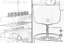
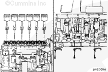
Remove the cylinder head. Refer to Procedure 002-004.
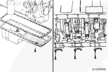
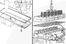
Drain the lubricating oil pan. Refer to Procedure 007-037.
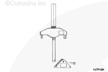
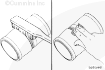
The liner puller must be installed and used as described to avoid damage to the cylinder block. The puller plate must be parallel to the main bearing saddles and must not overlap the liner outside diameter.
Insert the liner puller in the top of the cylinder block.
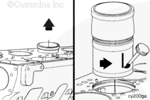
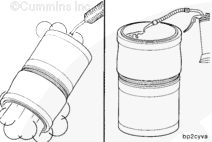
When the liner is removed from the cylinder block, use Dykem®, or equivalent, to place a mark on the camshaft side of the liner to show liner orientation.
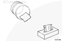
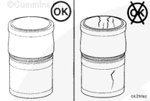
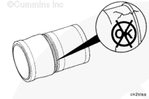
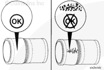
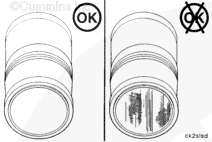
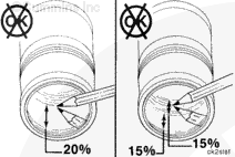
Inspect the outside diameter for excessive corrosion or pitting. Liners with pitting generally can not be reused. However, if the pitting is light and can be removed with fine emery cloth, the liner can be reused.
Pits must not be more than 1.60 mm [0.060 in] deep.
The current o-ring has been produced by two distinctly different manufacturing processes. Following are those two methods and the installation procedures:
The molded o-ring has a symmetrical cross section. The edges are rounded. It does not require specific care in orientation of the o-ring other than normal prevention of rolling the o-ring.
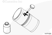
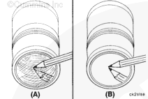
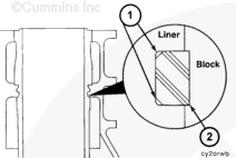
The lathe-cut o-ring has a straight outside with sharp corners. The inside has two 45-degree chamfers (1), so there are no sharp corners next to the liner. This o-ring must be installed with the straight side (2) facing the block, and the chamfered side next to the liner. If the o-ring is not installed this way, liner bore distortion can occur.
The liners must be installed within 30 seconds after being lubricated with oil. If the liners are not installed within this time limit, the o-rings will swell and be damaged when the liner is installed.
Make sure the cylinder block and all parts are clean before assembly.
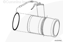
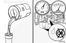
Use clean 15W-40 oil to coat the liner o-ring seals.
When acceptable reused liners are installed, rotate the liner 90 degrees from their original position in the engine. The thrust and anti-thrust surfaces must face the front and back of the cylinder block.
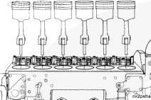
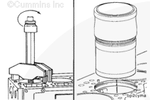
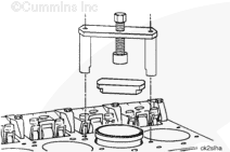
Use cylinder liner driver, Part Number 3824272, and a leather mallet to drive the liner into the cylinder block bore.
If the liner does not seat properly, remove the liner. Inspect the counterbore seat and liner for nicks, burrs, or dirt. Install the liner again.
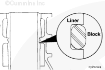
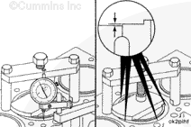
The cylinder liner protrusion must be checked before installing the pistons and connecting rods. Refer to Procedure 001-064 for measuring the cylinder liner protrusion.
Hello, I'm Jack, a diesel engine fan and a blogger. I write about how to fix and improve diesel engines, from cars to trucks to generators. I also review the newest models and innovations in the diesel market. If you are interested in learning more about diesel engines, check out my blog and leave your feedback.
View all posts by Jack


 CAUTION
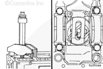


 WARNING


;)
;)
;)
;)
;)
;)
;)
;)
;)
;)
;)
;)
;)
;)
;)
;)
;)
;)
;)
;)
;)
;)
;)
;)
;)
;)
;)
;)
;)
;)
;)
;)
;)
;)
;)
;)
;)
;)
;)
;)
;)
;)
;)
;)
;)
;)
;)
;)
;)
;)
;)
;)
;)
;)