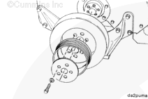
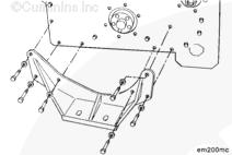
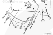
The lifting equipment must be designed to support the engine safely while the front engine support is removed from the engine. Failure to do so will result in equipment damage or personal injury.
Use an overhead hoist or hydraulic arm to support the engine.
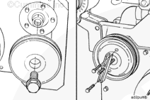
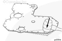
Remove the capscrews that hold the front engine support to the cross
member of the equipment.
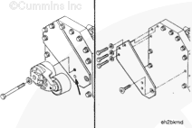
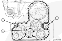
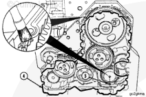
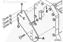
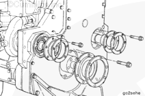
If the engine is equipped with an automatic belt tensioner, install the belt tensioner bracket with the countersunk hole (A) facing away from the gear cover. Use a flat head (M8 x 25) at location (A).
Use three capscrews (M8 x 30) and plain washers at (B, C, and D). Tighten the capscrews.
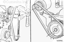
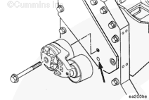
Install the automatic belt tensioner with a (M10-1.50 x 70) capscrew. Align the cast locator pin on the tensioner with the hole in the bracket before tightening.
Hello, I'm Jack, a diesel engine fan and a blogger. I write about how to fix and improve diesel engines, from cars to trucks to generators. I also review the newest models and innovations in the diesel market. If you are interested in learning more about diesel engines, check out my blog and leave your feedback.
View all posts by Jack


 WARNING
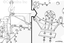


;)
;)
;)
;)
;)
;)
;)
;)
;)
;)
;)
;)
;)
;)
;)
;)
;)
;)
;)
;)
;)
;)
;)
;)
;)
;)
;)
;)
;)
;)
;)
;)
;)
;)
;)
;)
;)
;)
;)
;)
;)
;)
;)
;)
;)
;)