M11 Series – Service Manual – 001-033   Gear Housing, Front

Remove

TOC

Remove the alternator and alternator bracket.

Refer to Procedure 013-001.

SMALL | MEDIUM | LARGE


Remove the gear cover.

Refer to Procedure 001-031.

SMALL | MEDIUM | LARGE


Remove the accessory drive.

Refer to Procedure 009-001.

Remove the hydraulic pump, if equipped.

Refer to Procedure 009-016.

SMALL | MEDIUM | LARGE


Disconnect the engine position wire connector, and remove the engine position sensor from the backside of the housing.

SMALL | MEDIUM | LARGE


Remove the water pump.

Refer to Procedure 008-062.

SMALL | MEDIUM | LARGE


Remove the idler gears. Refer to the following:

Procedure 001-036,
Procedure 001-039,
and Procedure 001-040.

SMALL | MEDIUM | LARGE


Remove the camshaft gear or the camshaft and gear assembly. Refer to the following:

Procedure 001-012 for the camshaft gear,
Procedure 001-008 for the camshaft and gear assembly.

SMALL | MEDIUM | LARGE


Remove the four oil pan-to-gear housing capscrews.

SMALL | MEDIUM | LARGE


Remove the capscrews that secure the gear housing to the cylinder block.

NOTE: Be careful

not to damage the oil pan gasket when removing
the gear housing. If the gasket is damaged, the oil pan

must
be removed and the gasket replaced.

Remove the gear housing from the cylinder block.

SMALL | MEDIUM | LARGE


Use bearing driver kit, Part No. 3824117, to remove the water pump drive
needle bearing.

Use bearing puller kit, Part No. 3823774, to remove the hydraulic drive
needle bearing.

SMALL | MEDIUM | LARGE
   

Clean

TOC

Remove the RTV sealant from the rear surface of the gear housing.

Remove the seal in the grooves on the front surface of the gear housing.

Use a wire brush, rounded blade or screwdriver, to clean the grooves
on both sides.

SMALL | MEDIUM | LARGE


 WARNING 

When using a steam cleaner, wear protective clothing, and safety glasses or a face shield. Hot steam can cause serious personal injury.

Use steam or solvent to clean the gear housing and dry with compressed
air.

SMALL | MEDIUM | LARGE
   

Inspect for Reuse

TOC

Inspect the gear housing for cracks or other damage.

Inspect the seal grooves on both sides of the housing for debris or damage.

Inspect the o-ring groove at the accessory drive oil jumper gallery for cracks or damage.

Use compressed air to make sure the oil jumper gallery to the accessory
drive is free of any obstructions.

SMALL | MEDIUM | LARGE


Measure the inside diameter of the bearing bores at the accessory drive, water pump drive, and hydraulic drive.

Gear Housing Bearing Bore I.D.
mm in
Hydraulic Drive 41.967 MIN 1.6522
  41.992 MAX 1.6532
Water Pump 36.967 MIN 1.4553
  36.992 MAX 1.4564
Accessory Drive 45.100 MIN 1.7756
  45.125 MAX 1.7766

SMALL | MEDIUM | LARGE
   

Install

TOC

 CAUTION 

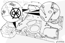
Avoid the use of excessive amounts of sealant, which could result in blocked oil passages in the engine.

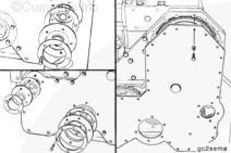
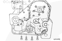
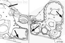
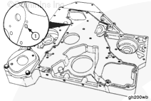
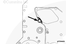
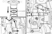
Install a new o-ring, Part No. 3883150, into the rear of the gear housing
at the oil jumper gallery (1) for the accessory drive support. Be sure to
keep sealant from the hole.

NOTE: Sealant requires assembly in 10 minutes or less. It is best to apply the sealant and then immediately assemble the parts.

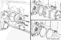
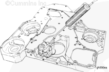
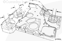
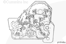
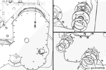
Apply a bead of sealant, Part No. 3823494, to the groove in the rear
of the gear housing. Completely fill the groove so that approximately 1/16
to 1/8 inch of the bead is raised above the block mounting surface of the
gear housing.

SMALL | MEDIUM | LARGE


Apply a 2-mm [1/6-in] bead of sealant, Part No. 3823494, to the oil
pan and cylinder block gear housing joint.

SMALL | MEDIUM | LARGE


Apply additional sealant in the area by the camshaft opening as shown in the graphic.

 
SMALL | MEDIUM | LARGE


Install two guide pins, Part No. 3376488, in the gear housing end of the cylinder block.

NOTE: Use care

not to damage the oil pan gasket while installing
the gear housing.

Install the gear housing and ten capscrews (M10-1.50 x 25) in the inner part of the gear housing.

Install five capscrews (M10-1.50 x 50) on the outer surface of the housing.

Remove the guide pins, and install the two remaining capscrews (M10-1.50 x 25).

SMALL | MEDIUM | LARGE


Tighten the capscrews in the sequence shown.

Torque Value: Step 1 20 n.m   [15 ft-lb]
  Step 2 68 n.m   [50 ft-lb]

SMALL | MEDIUM | LARGE


Install the four oil pan to gear housing capscrews.

Torque Value:  47  n.m  [35 ft-lb]

SMALL | MEDIUM | LARGE


Install the camshaft gear, or camshaft and gear assembly. Refer to Procedure

001-012 or

001-008, respectively.

SMALL | MEDIUM | LARGE


Use bearing driver kit, Part No. 3824117, to install a new needle bearing
in the water pump drive bore of the gear housing.

NOTE: The bearing

must be installed with the part number side
of the bearing against the installation tool to prevent damage to the bearing
during the installation.

Install the bearing from the front side of the gear housing until the
bearing is flush with the front edge of the housing bore.

SMALL | MEDIUM | LARGE


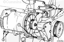
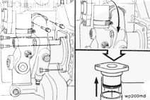
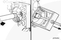
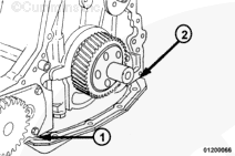
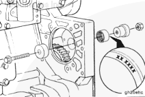
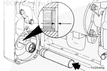
Use bearing installation tool, Part No. 3823776, included in bearing
puller kit, Part No. 3823774, to install a new needle bearing in the hydraulic
drive bore of the gear housing.

Tap the bearing gently until it comes in contact with the shoulder in
the housing.

The bearing

must be 0.25 to 0.76 [0.010 to 0.030 in] past
the outside edge of the gear housing bore surface.

SMALL | MEDIUM | LARGE


Install the idler gears. Refer to Procedures

001-036,

001-039, and

001-040.

SMALL | MEDIUM | LARGE


Install the water pump. Refer to Procedure

008-062.

SMALL | MEDIUM | LARGE


Install the engine position sensor in the backside of the gear housing.

Torque Value:  34  n.m  [25 ft-lb]

Connect the sensor to the engine wiring harness.

SMALL | MEDIUM | LARGE


Install the accessory drive. Refer to Procedure

009-001.

Install the hydraulic drive, if equipped. Refer to Procedure

009-016.

SMALL | MEDIUM | LARGE


Install the alternator bracket with two M10-1.50 x 30 capscrews.

Torque Value:  47  n.m  [35 ft-lb]

Install the alternator. Refer to Procedure

013-001.

SMALL | MEDIUM | LARGE


Install the gear cover. Refer to Procedure

001-031.

SMALL | MEDIUM | LARGE


Operate the engine to normal operating temperature and check for leaks.

SMALL | MEDIUM | LARGE
Last Modified:  05-Jul-2002