Remove
TOC
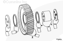
SAE ‘A’ and SAE ‘B’ Removal
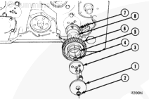
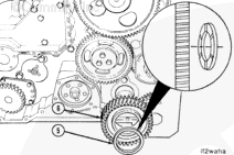
To remove the hydraulic drive idler gear assembly, remove:
Mounting spacer (1)
Rectangular seal (2)
The three twelve-point capscrews
Gear retainer (3)
Rectangular seal (4)
Front thrust bearing (5)
Idler gear (6)
Rear thrust bearing (7)
Idler gear shaft (8).
NOTE : SAE “A” drives do
not use a rectangular seal (4) on the
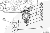
SAE ‘B-B’ Removal
To remove SAE B-B hydraulic drive idler gear assembly, remove:
Mounting Spacer (1)
Tapered Roller Bearing (2)
Gear Drive (3)
Tapered Roller Bearing (4)
Shim(s) (5)
Idler Gear Shaft (6)
Mounting Spacer (7)
Rectangular Seal (8).
Clean
TOC
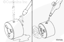
Use a bristle brush to clean the oil drillings in the idler gear shaft.
Blow out the oil drillings with compressed air.
Inspect for Reuse
TOC
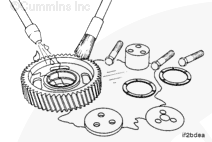
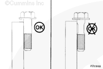
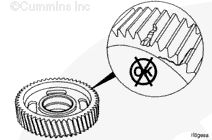
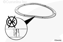
Use a straightedge to inspect the retaining capscrews for necking.
not reuse the capscrews. They
must be replaced.
NOTE : SAE ‘B-B’ hydraulic drive gear assembly does
not use thrust washers.
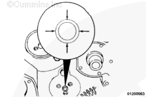
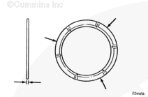
Measure the thrust washer thickness in three places 120-degrees apart.
Hydraulic Drive Idler Thrust Washer Thickness
mm
in
2.400
MIN
0.0945
2.470
MAX
0.0972
NOTE : SAE ‘B-B’ hydraulic drive gear assembly does
not use thrust washers.
Flex the thrust washers approximately 3 to 6 mm [1/8 to 1/4 in], and
Install
TOC
SAE ‘A’ and SAE ‘B’ Install
Use Lubriplate™ 105, or equivalent, to lubricate the thrust bearings and idler gear.
CAUTION
The grooved side of the rear thrust bearing must be facing toward the gear to prevent damage to the gear and engine during engine operation.
Install the idler gear shaft (8) and rear thrust bearing (7).
NOTE : When an SAE B drive is used, a special hydraulic drive idler shaft with
CAUTION
The grooved side of the front thrust bearing must be facing toward the gear to prevent damage to the gear and engine during engine operation.
Install the idler gear (6) and front thrust bearing (5).
NOTE : On SAE “B” drives, install a new rectangular seal on the rear surface
Install the gear retainer (4).
Install the three retaining capscrews and tighten.
Torque Value: Step 1
61 n.m [45 ft-lb]
SAE ‘B-B’ Install
NOTE : Use shim(s) as necessary for proper idler gear end clearance.
Use Lubriplate™ 105, or equivalent to lubricate the roller bearings and gear.
To install SAE B-B hydraulic drive idler gear assembly, install
Mounting Spacer (1)
Tapered Roller Bearing (2)
Gear Drive (3)
Tapered Roller Bearing (4)
Shim (s) (5)
Idler Gear Shaft (6)
Mounting Spacer (7)
Rectangular Seal (8).
Torque Value: Step 1
61 n.m [45 ft-lb]
The following idler gear end clearance and backlash checks apply to
MINIMUM and
MAXIMUM
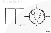
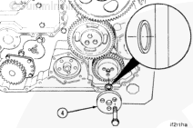
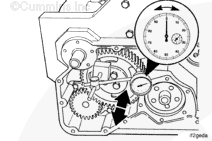
Use a dial indicator gauge with a magnetic base to measure the idler
Place the contact tip of the gauge against the face of the idler gear.
Idler Gear End Clearance
mm
in
0.30
MIN
0.012
0.53
MAX
0.021
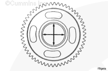
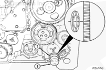
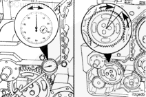
Use a dial indicator gauge with a magnetic base to measure the idler
Place the contact tip of the gauge against a tooth on the idler gear.
NOTE : Do
not allow the mating gears to move while measuring the backlash.
Idler Gear Backlash
mm
in
0.08
MIN
0.003
0.38
MAX
0.015
Last Modified: 05-Jul-2002
Published by Jack
Hello, I'm Jack, a diesel engine fan and a blogger. I write about how to fix and improve diesel engines, from cars to trucks to generators. I also review the newest models and innovations in the diesel market. If you are interested in learning more about diesel engines, check out my blog and leave your feedback.
View all posts by Jack


 CAUTION

;)
;)
;)
;)
;)
;)
;)
;)
;)
;)
;)
;)
;)
;)
;)
;)
;)
;)
;)
;)
;)
;)
;)
;)
;)
;)
;)
;)
;)
;)
;)
;)
;)
;)
;)
;)
;)
;)
;)
;)