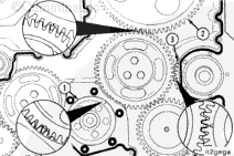
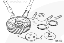
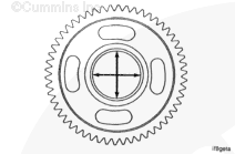
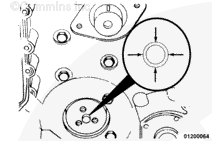
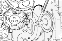
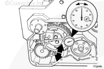
Before removing the idler gear, use the accessory driveshaft to rotate
the crankshaft until the timing marks on the crankshaft gear (1), camshaft
gear (2), and accessory drive gear (3) are completely engaged in the camshaft
idler gear.
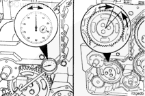
NOTE: Due to the camshaft idler gear having more gear teeth than the crankshaft
gear, the camshaft idler gear timing marks will
not align with the crankshaft, camshaft, and accessory drive gears timing marks on
every engine revolution.
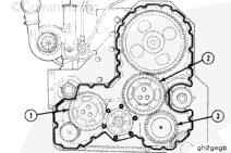
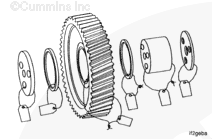
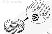
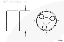
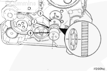
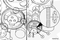
When installing the camshaft idler gear (1), make certain the timing
mark “0”on the crankshaft gear (2), timing mark “X”
on the camshaft gear (3), and timing mark “V” on the accessory drive gear (4) are aligned as shown.
The marks on the idler gears should match the same mark on each of the other gears.
Hello, I'm Jack, a diesel engine fan and a blogger. I write about how to fix and improve diesel engines, from cars to trucks to generators. I also review the newest models and innovations in the diesel market. If you are interested in learning more about diesel engines, check out my blog and leave your feedback.
View all posts by Jack


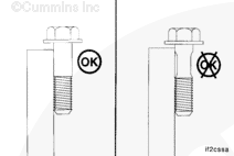

 CAUTION

;)
;)
;)
;)
;)
;)
;)
;)
;)
;)
;)
;)
;)
;)
;)
;)
;)
;)
;)
;)
;)
;)
;)
;)
;)
;)
;)
;)
;)
;)
;)
;)
;)
;)
;)
;)
;)
;)
;)
;)