Remove
TOC
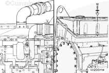
Remove the gear cover.
Refer to Procedure 001-031.
NOTE : It is possible to remove the camshaft without removing the cylinder
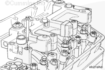
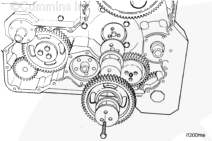
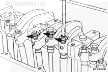
Raise the cam follower assemblies, and use a wire to tie the cam followers
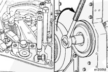
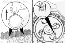
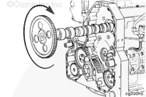
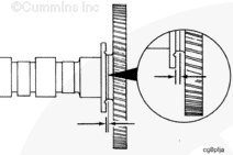
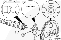
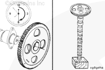
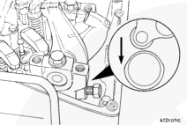
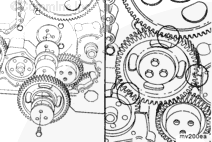
Rotate the camshaft to align the holes in the camshaft gear with the
Remove the thrust plate capscrews.
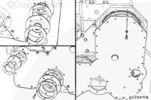
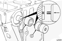
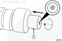
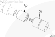
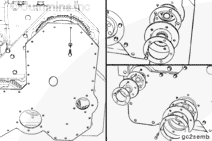
Install the arbor sleeve (2) over the expander.
Install the locating pilot extensions (3) to the expander.
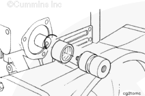
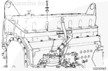
Use one hand to rotate slowly and pull the camshaft from the cylinder
Remove the camshaft pilot tool.
Clean
TOC
WARNING
When using a steam cleaner, wear protective clothing, as well as, safety glasses or a face shield. Hot steam can cause serious personal injury.
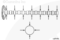
Clean the camshaft with steam or solvent. Dry with compressed air.
CAUTION
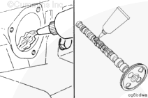
After the camshaft has been steam cleaned, do not touch the machined surfaces with bare hands. This will cause rust to form, which will damage the camshaft. Lubricate the camshaft with clean 15W-40 oil before handling.
Install
TOC
Install the arbor sleeve (2) over the expander.
Install the locating pilot extensions (3) to the expander.
The camshaft installation pilot
must be disassembled as
Remove the camshaft pilot.
Rotate the camshaft to align the holes in the camshaft gear with the
Align the capscrew holes in the thrust plate with the cylinder block
Install the capscrews.
Torque Value: 47 n.m [35 ft-lb]
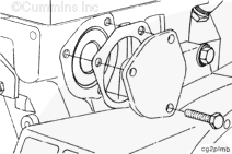
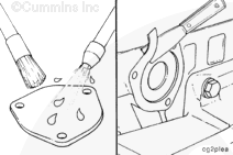
Use a new gasket to install the camshaft rear cover plate.
Tighten the three capscrews.
Torque Value: 47 n.m [35 ft-lb]
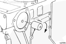
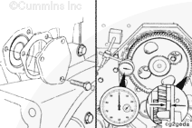
Measure the camshaft end clearance.
Camshaft End Clearance
mm
in
0.13
MIN
0.005
0.33
MAX
0.013
Do
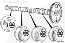
not drop the cam follower levers on the camshaft lobes.
Carefully lower the cam followers onto the camshaft.
Operate the engine to normal operating temperature and check for leaks.
Last Modified: 07-May-2003
Published by Jack
Hello, I'm Jack, a diesel engine fan and a blogger. I write about how to fix and improve diesel engines, from cars to trucks to generators. I also review the newest models and innovations in the diesel market. If you are interested in learning more about diesel engines, check out my blog and leave your feedback.
View all posts by Jack


 WARNING
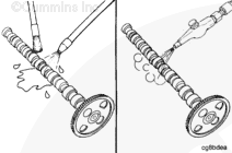
 CAUTION
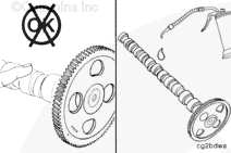


;)
;)
;)
;)
;)
;)
;)
;)
;)
;)
;)
;)
;)
;)
;)
;)
;)
;)
;)
;)
;)
;)
;)
;)
;)
;)
;)
;)
;)
;)
;)
;)
;)
;)
;)
;)
;)
;)
;)
;)
;)
;)
;)
;)
;)
;)
;)
;)
;)
;)
;)
;)
;)
;)
;)
;)
;)
;)
;)
;)