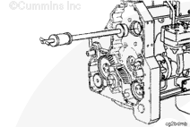
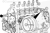
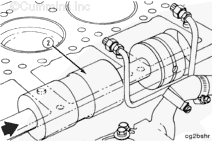
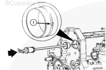
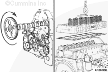
Use Part No. 3376637, camshaft bushing driver and Part No. 3367636 Driver, or Part No. 3823642, hydraulic cam bushing tool, and Part No. 3823621 hydraulic actuator kit to remove the camshaft bushings.
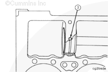
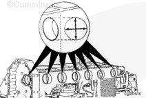
The bushing oil groove must be visible in both cylinder block oil drillings (5 and 6) to prevent engine damage. The oil drillings are not in alignment with each other.
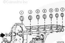
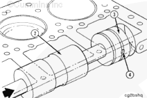
Inspect the bushing oil groove alignment with the two oil drillings
in the block as the bushing is installed.
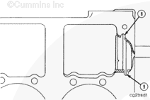
The bushing oil groove must be visible in both block oil drillings (8 and 9) to prevent engine damage. The block oil drillings are not in alignment with each other.
Hello, I'm Jack, a diesel engine fan and a blogger. I write about how to fix and improve diesel engines, from cars to trucks to generators. I also review the newest models and innovations in the diesel market. If you are interested in learning more about diesel engines, check out my blog and leave your feedback.
View all posts by Jack


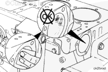


 CAUTION
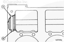
;)
;)
;)
;)
;)
;)
;)
;)
;)
;)
;)
;)
;)
;)
;)
;)
;)
;)
;)
;)
;)
;)
;)
;)
;)
;)
;)
;)
;)
;)
;)
;)