The puller assembly is heavy. Use a lifting device when securing it to the cam gear.
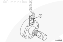
Make sure the forcing screw pilot is engaged with the center of the camshaft and the puller adapter assembly studs are properly seated in the holder plate assembly.
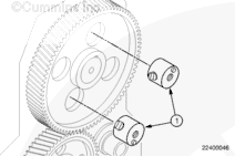
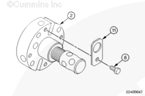
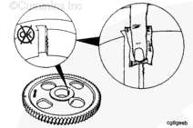
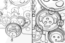
Using the lifting device, position the holder plate (2) against the cam gear and install two screws (7) through the holder plate (2) into the puller adapters (1).
Cam gear and puller assembly may fall when released and cause serious personal injury.
Do not attempt to alter the puller assembly for use with any kind of impact wrench. The threads on the puller assembly may gall and seize.
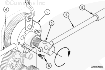
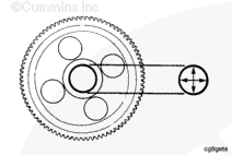
Use the lever bar (4), extension bar (5), and torque reaction lever (6), to turn the forcing screw (3) clockwise, pulling the cam gear from the camshaft.
Gear housing clearance makes key installation more difficult. Use care in seating the key.
Be sure the gear mounting surface is clean and free of oil, dirt, or debris.
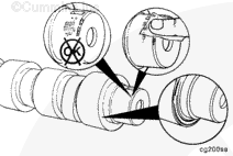
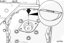
If the camshaft gear is used again, use the same part number key as the one that was removed. Be sure the arrow on the key is pointing in the same direction as when it was removed.
Use a leather hammer to install the camshaft gear key.
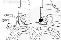
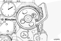
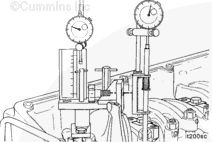
It can be necessary to remove the camshaft rear cover plate and apply pressure to the end of the camshaft to hold it in the forward position while the gear is being installed. Refer to Procedure 001-008.
Use insulated gloves, Part Number 3823730, and/or hot clamp pliers, Part Number 3823732, when handling heated parts. Hot parts can cause serious personal injury.
CAUTION
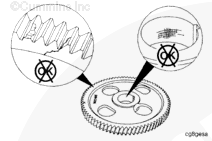
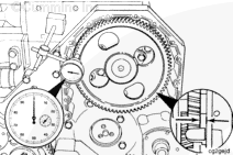
The timing marks and gear part number must be facing away from the camshaft when the gear is installed to prevent engine damage.
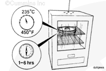
Use Lubriplate™ 105, or equivalent, to coat the camshaft nose before installing the camshaft gear.
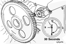
Remove the gear from the oven. Install the gear on the camshaft within 30 seconds after removing from the oven.
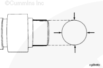
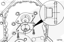
Align the gear keyway with the key in the camshaft, and install the gear on the camshaft.
Hello, I'm Jack, a diesel engine fan and a blogger. I write about how to fix and improve diesel engines, from cars to trucks to generators. I also review the newest models and innovations in the diesel market. If you are interested in learning more about diesel engines, check out my blog and leave your feedback.
View all posts by Jack


 WARNING
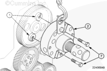


 CAUTION
;)
;)
;)
;)
;)
;)
;)
;)
;)
;)
;)
;)
;)
;)
;)
;)
;)
;)
;)
;)
;)
;)
;)
;)
;)
;)
;)
;)
;)
;)
;)
;)
;)
;)
;)
;)
;)
;)
;)
;)
;)
;)
;)
;)
;)
;)