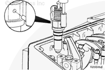
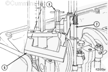
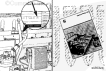
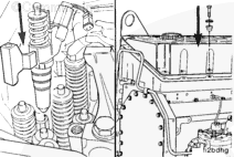
Install the injector push rod (9) between the injector camshaft follower and the plunger rod.
The push rod (9) must be vertically aligned with the plunger rod. If it is not, incorrect timing values will result. Be careful not to drop the push rod into the engine.
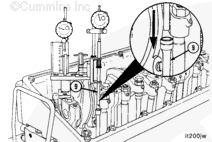
Use the accessory driveshaft to rotate the crankshaft. If another method is used, the injection timing will not be correct, or the engine can be damaged.
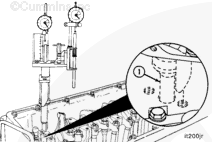
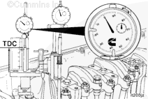
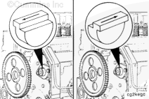
Determine the piston top dead center (TDC) on the compression stroke by rotating the accessory driveshaft clockwise.
The piston is on the compression stroke when both plungers move in an upward direction at the same time. Top dead center is indicated by the maximum clockwise indicator position of the piston travel indicator pointer.
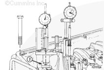
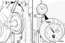
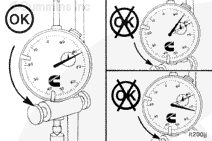
Rotate the accessory driveshaft back and forth, before and after the zero “0” indicator reading, for approximately 3 degrees to be sure the piston is at top dead center.
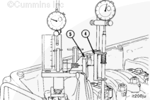
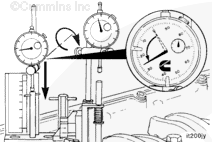
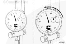
Position the push rod dial indicator contact tip in the center of the plunger rod, and lower the gauge to with in 0.63 mm [0.025 in] of the fully compressed position.
Set the push rod dial indicator to zero “0.”
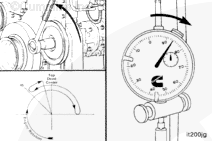
Rotate the accessory driveshaft counterclockwise to top dead center.
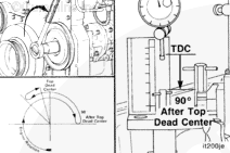
Continue to rotate the accessory driveshaft counterclockwise until the crankshaft is at 45-degrees before top dead center (BTDC). This step is necessary to remove gear backlash in the engine.
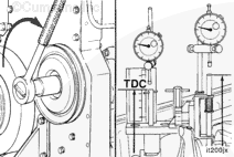
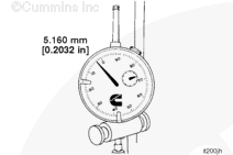
Rotate the accessory driveshaft clockwise slowly until the piston travel gauge is at 5.160-mm [0.2032-in] before top dead center.
If the crankshaft is rotated beyond the 5.160-mm [0.2032- in] BTDC position, the crankshaft must be rotated counterclockwise back to the 45-degrees before top dead center mark.
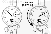
Read the push rod travel gauge counterclockwise from zero “0.” This travel represents the injection timing value. In the example shown, the value is 1.98-mm [0.078-in].
To verify the correct injection timing for a particular engine, check the Control Parts List (CPL) number on the engine dataplate. Refer to the CPL Manual, Bulletin 3379133. Timing codes are listed as two alphabetical characters.
Hello, I'm Jack, a diesel engine fan and a blogger. I write about how to fix and improve diesel engines, from cars to trucks to generators. I also review the newest models and innovations in the diesel market. If you are interested in learning more about diesel engines, check out my blog and leave your feedback.
View all posts by Jack


 CAUTION
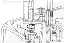


;)
;)
;)
;)
;)
;)
;)
;)
;)
;)
;)
;)
;)
;)
;)
;)
;)
;)
;)
;)
;)
;)
;)
;)
;)
;)
;)
;)
;)
;)
;)
;)
;)
;)
;)
;)
;)
;)
;)
;)
;)
;)
;)
;)