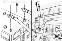
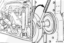
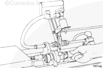
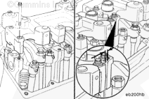
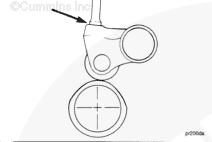
Use your fingers or a screwdriver to press the engine brake housing oil connector into the front brake housing to allow clearance for the housing removal.
Loosen the injector and valve adjusting screws and remove the push rods and push tubes on the cylinder requiring injector replacement.
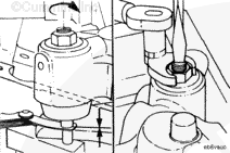
Some push rods are under compression due to the valves being open. Rotate the crankshaft clockwise with the accessory drive pulley to relieve the spring tension.
Mark the position of the push rods and push tubes as they are removed. Due to wear patterns on the cam follower sockets and adjusting screws, the push rods and push tubes must be installed in the same positions from which they are removed.
Hold the push rod with one hand to prevent it from falling into the engine. Loosen each adjusting screw and remove the push rod.
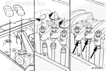
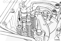
Remove the crossheads. Mark the position and orientation of the crossheads as they are removed. Due to wear patterns, they must be installed in the same positions from which they are removed.
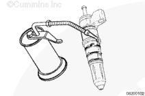
Disconnect the injector wires. Number the injector electrical connections as they are removed. They must be connected to the same cylinder when they are installed.
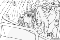
Remove the clamp capscrew and injector hold down clamp.
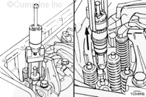
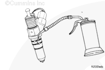
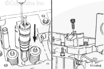
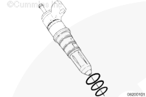
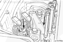
Use Injector Puler/Installer service tool, Part Number 3823579, to remove the injectors. Insert the pin of the tool into the hole provided in the body of the injector.
Use your fingers or a screwdriver to press the engine brake housing oil connector into the front brake housing to allow clearance for the housing removal.
Loosen the injector and valve adjusting screws and remove the push rods and push tubes on the cylinder requiring injector replacement.
Some push rods are under compression due to the valves being open. Rotate the crankshaft clockwise with the accessory drive pulley to relieve the spring tension.
Mark the position of the push rods and push tubes as they are removed. Due to wear patterns on the cam follower sockets and adjusting screws, the push rods and push tubes must be installed in the same positions from which they are removed.
Hold the push rod with one hand to prevent it from falling into the engine. Loosen each adjusting screw and remove the push rod.
Remove the crossheads. Mark the position and orientation of the crossheads as they are removed. Due to wear patterns, they must be installed in the same positions from which they are removed.
Disconnect the injector wires. Number the injector electrical connections as they are removed. They must be connected to the same cylinder when they are installed.
Remove the clamp capscrew and injector hold down clamp.
Use Injector Puller/Installer service tool, Part Number 3823579, to remove the injectors. Insert the pin of the tool into the hole provided in the body of the injector.
NOTE: Mark the position of the push rods as they are removed. Due to wear patterns on the cam follower sockets and adjusting screws, the push rods must be installed in the same positions from which they are removed.
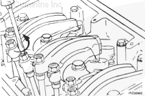
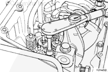
Loosen the locknut and turn out the adjusting screw on each injector and valve rocker lever.
Some push rods are under compression due to the valves being open. Rotate the crankshaft clockwise with the accessory drive pulley to relieve the spring tension.
Hold the push rod with one hand to prevent it from falling into the engine. Loosen each adjusting screw and remove the push rod.
NOTE: Do not remove the links from step timing control injectors.
Rotate the injector and valve rocker levers up on each cylinder.
Remove the crossheads. Mark the position and orientation of the crossheads as they are removed. Due to wear patterns, they must be installed in the same positions from which they are removed.
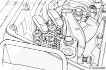
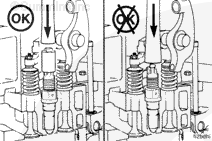
Do not drive the injector in by striking the solenoid valve area. This can damage the solenoid or cause the injector to be out of alignment in the bore which will result in o-ring damage.
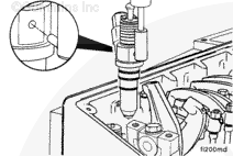
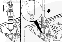
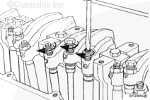
Place the injector in the cylinder head injector bore with the injector solenoid valve toward the intake port. Align the injector equally between the valve springs.
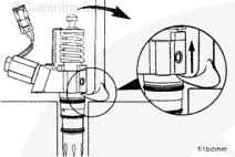
Use Injector Puller/Installer service tool, Part Number 3823579, to seat the injector in the bore.
The injector must be fully seated before installing the hold down clamp. The hold down clamp can not pull the injector into the bore. Engine damage can occur if the injector is not fully seated.
Install the injector hold down clamp capscrew.
Torque Value: 75 n.m [55 ft-lb]
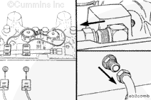
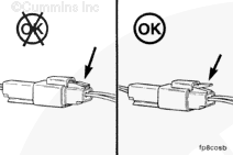
Connect the injector wires. Make sure the wires are connected to the same cylinder they were removed from.
Check the wire connector to make sure the connector is properly locked in position.
If the wire connector will not properly lock into position, refer to the Troubleshooting and Repair Manual, CELECT™ Plus Fuel System, Bulletin 3666130.
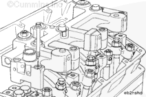
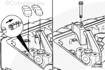
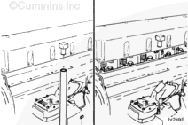
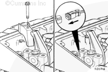
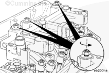
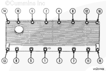
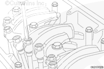
Install the 16 isolators and capscrews. Tighten the capscrews in the sequence shown.
Torque Value: 15 n.m [130 in-lb]
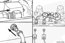
Install the crankcase breather tube. Install the air piping from the charge air cooler to the intake manifold. Refer to the manufacturer’s specifications for the correct hose clamp torque value.
Do not drive the injector in by striking the solenoid valve area. This can damage the solenoid or cause the injector to be out of alignment in the bore which will result in o-ring damage.
Place the injector in the cylinder head injector bore with the injector solenoid valve toward the intake port. Align the injector equally between the valve springs.
Use Injector Puller/Installer service tool, Part Number 3823579, to seat the injector in the bore.
The injector must be fully seated before installing the hold down clamp. The hold down clamp can not pull the injector into the bore. Engine damage can occur if the injector is not fully seated.
Install the injector hold down clamp capscrew.
Torque Value: 75 n.m [55 ft-lb]
Connect the injector wires. Make sure the wires are connected to the same cylinder they were removed from.
Check the wire connector to make sure the connector is properly locked in position.
If the wire connector will not properly lock into position, refer to the Troubleshooting and Repair Manual, CELECT™ Plus Fuel System, Bulletin 3666130.
Install the 16 isolators and capscrews. Tighten the capscrews in the sequence shown.
Torque Value: 15 n.m [130 in-lb]
Install the crankcase breather tube. Install the air piping from the charge air cooler to the intake manifold. Refer to the manufacturer’s specifications for the correct hose clamp torque value.
Install a set of new injectors using the 8-qt 10-hole cup configuration that was removed from the engine. This will make sure that the injectors will not have any unseen cavitation damage internal to the injector cup at the time of kit installation.
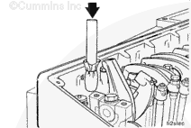
Make sure to place the instrument used to install the injectors on the top cap of the injector, not on the plunger or link. The plungers will be damaged.
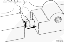
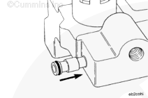
Install a 27-mm [1-1/16-in] deep well socket over the top link of the injector. The socket must rest completely on the top surface of the injector top cap to avoid bending the inner part of the top cap.
Use a clean, blunt instrument to seat the injector in the bore.
The injector must be fully seated before installing the hold-down clamp. The hold-down clamp can not pull the injector into the bore. Engine damage can occur if the injector is not fully seated.
Install the injector hold-down clamp and capscrew.
Hello, I'm Jack, a diesel engine fan and a blogger. I write about how to fix and improve diesel engines, from cars to trucks to generators. I also review the newest models and innovations in the diesel market. If you are interested in learning more about diesel engines, check out my blog and leave your feedback.
View all posts by Jack


 CAUTION
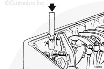


;)
;)
;)
;)
;)
;)
;)
;)
;)
;)
;)
;)
;)
;)
;)
;)
;)
;)
;)
;)
;)
;)
;)
;)
;)
;)
;)
;)
;)
;)
;)
;)
;)
;)
;)
;)
;)
;)
;)
;)
;)
;)
;)
;)
;)
;)
;)
;)
;)
;)
;)
;)
;)
;)
;)
;)
;)
;)
;)
;)
;)
;)
;)
;)
;)
;)
;)
;)
;)
;)
;)
;)
;)
;)
;)
;)
;)
;)