M11 Series – Service Manual – 005-999   Fuel System – Overview

General Information

TOC

SMALL | MEDIUM | LARGE

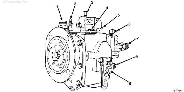
PT (TYPE G) AFC FUEL PUMP

  1. Tachometer Drive
  2. AFC Air Supply
  3. Fuel to Injectors
  4. Priming Plug
  5. Shutoff Valve Electric Connection
  6. Gear Pump Cooling Fitting
  7. Fuel Inlet Connection
  8. Idle Speed Screw Location
  9. Fuel Rate (Pressure) Screw

SMALL | MEDIUM | LARGE

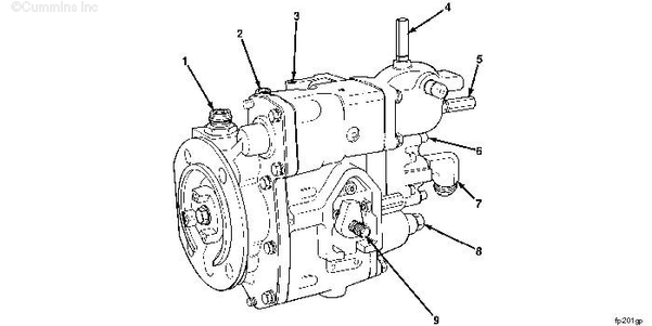
PT (TYPE G) AFC VS FUEL PUMP

  1. Tachometer Drive
  2. AFC Air Supply
  3. Fuel to Injectors
  4. VS High Speed Screw
  5. VS Low (Idle) Speed Screw
  6. Gear Pump Cooling Fitting
  7. Fuel Inlet Connection
  8. Idle Speed Screw Location
  9. Fuel Rate (Pressure) Screw

The PT fuel system is used exclusively on Cummins diesels. The identifying letters “PT” are an abbreviation of pressure-time.

The STC system is used on Cummins diesels to advance the injection timing under idle or light load conditions.

The STC system includes fuel pump, supply lines, drain lines, fuel passages, oil passages, check valves, STC oil control valve, and STC injectors.

NOTE: Refer to Procedures 006-026 (Injector) , 006-024 (Fuel Supply Lines), and 006-037 (STC Oil Control Valve (Mechanical)) in Section 6, for repairs to the STC injectors, fuel lines, and STC oil control valve.

The CELECT™ and CELECT™ Plus fuel systems are used exclusively on Cummins diesels.

The CELECT™ and CELECT™ Plus fuel systems consist of the fuel pump, Electronic Control Module (ECM), ECM cooling plate, supply lines, drain lines, engine wiring harness, sensors, and injectors.

NOTE: For repairs to the CELECT™ or CELECT™ Plus sensors, ECM, and engine wiring harness, refer to Procedures 019-004 (Barometric Air Pressure Sensor), 019-017 (Engine Coolant Level Sensor), 019-019 (Engine Coolant Temperature Sensor), 019-038 (Engine Position Sensor (EPS)), 019-059 (Intake Manifold Air Temperature Sensor), 019-061 (Intake Manifold Pressure Sensor), 019-091 (Vehicle Speed Sensor, Magnetic Pick Up), 019-134 (Ambient Ait Temperature Sensor), 019-031 (Electronic Control Module (ECM)), and 019-043 (Engine Wiring Harness) in Section 19 of the Troubleshooting and Repair Manual CELECT™ Plus engines, Bulletin 3666130.

Installation Recommendations

TOC

Installation Publications

The following publications are available to provide fuel system installation recommendations approved by Cummins Inc.:

Automotive Installation Recommendations (Fuel System), Bulletin 3382707.

Contact the nearest Cummins Authorized Repair Location for engine fuel system specifications and requirements provided on the “Engine Data Sheet” for your specific engine and application.

SMALL | MEDIUM | LARGE


Overhead Fuel Tank Requirements

If the fuel filter is lower than the fuel pump, install a check valve in the filter outlet fuel line. Refer to the OEM Installation Recommendations.

The check valve on the outlet side of the fuel filter prevents gear pump fuel drainback during filter removal.

Install a shutoff valve between the filter and the fuel tank.

SMALL | MEDIUM | LARGE


 WARNING 

Fuel is flammable. Keep all cigarettes, flames, pilot lights, arcing equipment, and switches out of the work area and areas sharing ventilation to reduce the possibility of severe personal injury or death when working on the fuel system.

If the fuel line valve is not used, the overhead tank can drain when the fuel filter is changed. Spilled fuel is a fire hazard.

 
SMALL | MEDIUM | LARGE


Proper Use of Fuel System Gauges

NOTE: To be sure the reading is correct, always remove the air from the pressure gauge line before taking a reading.

Loosen the connection at the gauge to remove the air.

NOTE: Do not loosen the vacuum gauge connections when the engine is operating.

 
SMALL | MEDIUM | LARGE


Read the gauge in direct alignment with the gauge hand.

SMALL | MEDIUM | LARGE


Read the flow meter in direct alignment with the float.

NOTE: Read the level of the floats where indicated.

SMALL | MEDIUM | LARGE


Portable fuel pressure gauges must be checked regularly against a reference gauge or against the gauge on the fuel pump test stand. Adjust the valve on the gauge until the gauge needle stops vibrating.

SMALL | MEDIUM | LARGE


When measuring the fuel inlet and drain line restriction, the manometer or gauges must be on the same level as the connection point.

SMALL | MEDIUM | LARGE


NOTE: Always use the same size and material of line or hoses as was originally supplied with the gauge.

SMALL | MEDIUM | LARGE


The distance from the gauge to the connection point must be as short as possible.

SMALL | MEDIUM | LARGE


 CAUTION 

Never exceed the maximum capacity of the gauge or flow meter. If the maximum is exceeded, check the gauge against a reference gauge.

SMALL | MEDIUM | LARGE
Last Modified:  01-Aug-2007