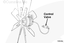
This procedure tests the correct operation of the fan, shutter, coolant temperature gauge, and thermostat. It also checks for combustion leaks into the cooling system, coolant flow through the filter, and entrained air in the system. Carefully read and understand all the following steps before beginning the troubleshooting procedure.
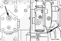
This is a free-running (non-dyno) test. It requires the use of the coolant pressure/temperature/flow analyzer kit, Part No. 3822994, and the proper installation of the cooling system Compuchek® fittings located on the engine.
Do not attempt to install fittings unless the coolant temperature is below 49°C [120°F]. Failure to do so can cause personal injury from heated coolant.
The coolant
must not be drained to install the fittings. Draining the engine can introduce air into the system and give false results.
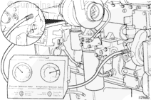
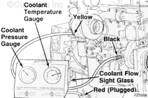
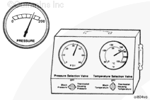
Pressure Readings
– Turn the pressure selection valve to the position corresponding to the desired reading. Turn the temperature selection valve to the “OFF” position.
NOTE: When the cylinder block pressure reading is taken, the valve
must
be turned to the thermostat housing pressure location. This is due to the different hose connection used on the M11 and L10 engines.
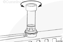
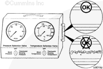
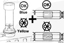
Monitor the sight glass installed on the service tool throughout the test. If air is observed, finish the test and examine the combustion leak tester. This will determine the origin of the leak. Refer to Procedure
Temperature Readings
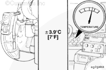
– There will be temperature fluctuations when switching the temperature selection valve. This fluctuation is normal, and is caused by temperature loss in the line. The temperature will stabilize after a few seconds.
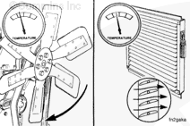
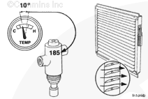
Fill in the blanks with the test data as the test is being run. Mark when the radiator line gets hot, when the fan starts operating, and when the shutters open.
Check the color of fluid in the combustion gas leak tester. This information, along with the sight glass observations, will help isolate the source of air in the cooling system, if any.
Check the recorded coolant temperature when the shutters are opened. Compare this value to that which is stamped on the shutter control. Cummins Engine Company, Inc. recommends that the shutters open at 85°C [185°F].
Check the recorded coolant temperature when the fan is engaged. Compare this value to that which is stamped on the fan control. Cummins Engine Company, Inc. recommends that the fan engage at 96°C [205°F].
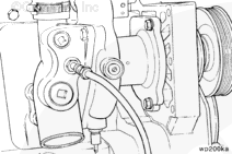
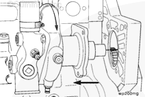
Read the recorded block pressure at 60°C [140°F]. If the block pressure is less than 138 kPa [20 psi] at high idle and without a pressure cap, check the following:
Remove the water pump, and inspect the impeller’s integrity and for slippage on the shaft.
Hello, I'm Jack, a diesel engine fan and a blogger. I write about how to fix and improve diesel engines, from cars to trucks to generators. I also review the newest models and innovations in the diesel market. If you are interested in learning more about diesel engines, check out my blog and leave your feedback.
View all posts by Jack
 WARNING
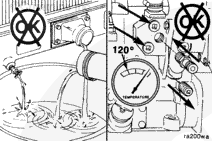


;)
;)
;)
;)
;)
;)
;)
;)
;)
;)
;)
;)
;)
;)
;)
;)
;)
;)
;)
;)
;)
;)
;)
;)
;)
;)
;)
;)
;)
;)