Remove
TOC
Drain the cooling system. Refer to Procedure
008-018-005 .
Disconnect the battery.
NOTE : If the coolant is
not
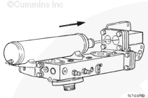
Remove the turbocharger oil supply tube, the bypass filter return tube, the turbocharger drain tube, and the turbocharger.
Remove the oil filter and the coolant filter.
For those engine applications utilizing the low mount oil cooler arrangement, follow the same procedure.
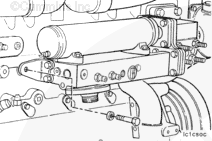
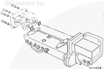
Remove the remaining five capscrews from the oil cooler support, and remove the cooler assembly.
WARNING
Because this part weighs more than 23 kg [50 lb], two people or a hoist will be required to lift the oil cooler assembly to avoid personal injury.
Clean
TOC
Clean the gasket material from the cooler support and the cylinder block.
After removing the gasket material, clean with solvent and dry with compressed air.
NOTE : Do
not
CAUTION
Do not attempt to repair a damaged oil cooler core; it must be replaced.
Pressure Test
TOC
CAUTION
Do not reuse an oil cooler core after an engine failure since there is not a practical method to clean the cooler core. Metal particles which can circulate through the lubricating system can remain in the cooler core and can cause engine damage. Do not allow dirt or gasket material to enter the oil passages when cleaning the oil cooler and the cylinder block surface.
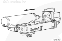
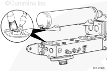
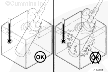
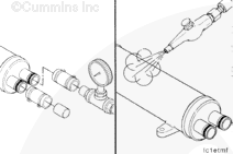
Install and clamp a short section of hose over either the inlet or outlet transfer tube of the oil cooler. Install a plug into the
opposite
Remove the oil cooler core from the water tank.
Remove the hoses and the clamps from the oil cooler.
Use lubricating oil to flush the oil side of the cooler to remove all the water.
Dry the oil cooler with compressed air.
Install
TOC
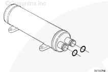
Install the connection retainer and o-rings adapters with new o-rings. Do
not
must
NOTE : Be careful to keep o-rings in place when installing the adapters and retainer.
Install the oil cooler core mounting gaskets and holddown capscrews.
Tighten the holddown capscrews.
Torque Value: 27 n.m [20 ft-lb]
Alternately tighten the connection retainer capscrews.
Torque Value: 47 n.m [35 ft-lb]
Install two guide studs into the oil cooler support mounting holes in the cylinder block.
Install a new oil cooler support gasket over the guide studs with the side marked “Cooler Side” facing outward or visible.
For those engine applications utilizing the low mount oil cooler arrangement, follow the same installation procedure.
Install the oil cooler assembly over the guide studs, and push it against the cylinder block.
Install the oil cooler support bracket capscrew. Do
not
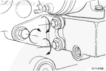
Install four of the support mounting capscrew, and remove the two guide studs.
Install the two remaining capscrews, and tighten all support capscrews.
Torque Value: 47 n.m [35 ft-lb]
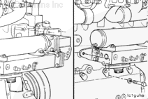
First, loosen the two capscrews which hold the oil cooler support bracket to the rear of the oil cooler housing.
Then, alternately and evenly, tighten the block mounting capscrew and the oil cooler housing capscrews beginning with the block mounting capscrew.
Torque Value: 47 n.m [35 ft-lb]
Install the turbocharger, turbocharger oil supply tube, the bypass filter return tube, and the turbocharger drain tube. Refer to Procedure
010-033-026 .
Fill and install a new oil filter and coolant filter. Refer to Procedures
007-013-026 and
008-006-026 , respectively.
Fill the cooling system. Refer to Procedure
008-018-028 .
Check to make sure the lubricating oil system is full. Prelubricate the system.
Operate the engine at low idle until the oil pressure comes up to 69 kPa [10 psi] minimum.
Operate the engine at high idle until the water temperature reaches 82°C [180°F], and check for oil and coolant leaks.
Last Modified: 12-May-2003
Published by Jack
Hello, I'm Jack, a diesel engine fan and a blogger. I write about how to fix and improve diesel engines, from cars to trucks to generators. I also review the newest models and innovations in the diesel market. If you are interested in learning more about diesel engines, check out my blog and leave your feedback.
View all posts by Jack


 WARNING
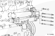


 CAUTION
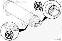


;)
;)
;)
;)
;)
;)
;)
;)
;)
;)
;)
;)
;)
;)
;)
;)
;)
;)
;)
;)
;)
;)
;)
;)
;)
;)
;)
;)
;)
;)
;)
;)
;)
;)
;)
;)
;)
;)
;)
;)
;)
;)
;)
;)
;)
;)
;)
;)
;)
;)