Some state and federal agencies have determined that used engine oil can be carcinogenic and cause reproductive toxicity. Avoid inhalation of vapors, ingestion, and prolonged contact with used engine oil. If not reused, dispose of in accordance with local environmental regulations.
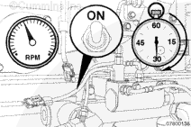
Fill the make-up tank to the full mark with clean engine oil.
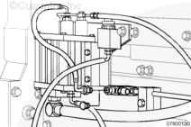
With the engine not running, disconnect the oil burn hose at the fuel return line fitting.
Plug the fuel return line to prevent fuel leakage.
If a make-up system is being serviced, disconnect the clean oil hose at the block fitting. Do not disconnect the used oil supply hose that is attached to a fitting in the oil rifle.
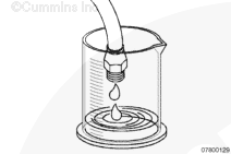
Use a graduated cylinder or other measuring container to capture the oil.
One full cycle will consist of one discharge of oil measuring 34 ml
+/- 4 ml from the oil burn hose and four discharges totaling 150 ml +/- 10 ml from the oil drain (or clean oil) hose. Capturing more than one cycle and taking an average of the oil output is recommended to minimize measurement error. These flow values are for both burn only and make-up systems.
The control valve must be rebuilt or replaced if the oil discharge is not within specification.
If the Centinel™ valve is found to be operating properly and too much oil is being used from the crankcase, verify regular engine oil consumption of the engine.
The Centinel™ system must first be isolated from the engine. This is done by disconnecting all Centinel™ oil lines from the engine and plugging all open ports.
Refer to the Lubricating Oil Consumption Excessive symptom chart in the appropriate troubleshooting and repair manual for further troubleshooting information.
Some state and federal agencies have determined that used engine oil can be carcinogenic and cause reproductive toxicity. Avoid inhalation of vapors, ingestion, and prolonged contact with used engine oil. If not reused, dispose of in accordance with local environmental regulations.
NOTE: Some single piston Centinel™ systems can use a service plug and do not need to be cycled manually.
Fill the make-up tank to the full mark with clean engine oil.
With the engine not running, disconnect the oil burn hose at the fuel return line fitting or integrated fuel system module (IFSM) port.
Plug the open port to prevent fuel leakage.
If a make-up system is being serviced, disconnect the clean oil hose at the block fitting. Do not disconnect the used oil supply hose that is attached to a fitting in the oil rifle.
Cycle the solenoid several times. Each full cycle should discharge 17 ml +/- 3 ml from each oil line. Divide the total oil volume by the number of cycles to get an average reading.
The control valve must be rebuilt or replaced if the oil discharge is not within specification.
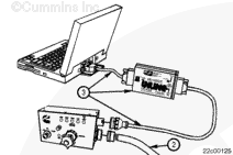
Use the Cummins INSITE™ electronic service tool to clear all inactive Centinel™ fault codes in the ECM. Refer to the appropriate INSITE™
User’s Manual.
If the Centinel™ valve is found to be operating properly and too much oil is being used from the crankcase, verify regular engine oil consumption of the engine.
The Centinel™ system must first be isolated from the engine. This is done by disconnecting all Centinel™ oil lines from the engine and plugging all open ports.
Refer to the Lubricating Oil Consumption Excessive symptom chart in the appropriate troubleshooting and repair manual for further troubleshooting information.
Batteries can emit explosive gases. To reduce the possibility of personal injury, always ventilate the compartment before servicing the batteries. To reduce the possibility of arcing, remove the negative (-) battery cable first and attach the negative (-) battery cable last.
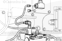
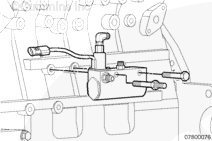
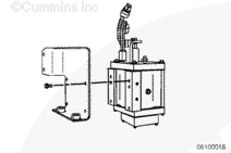
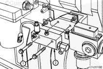
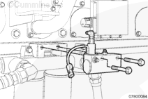
Install the Centinel™ oil control valve on the ISM engine block using the one studded M10 x 1.5 and one flange head M10 x 1.5 capscrews. The capscrews insert through the two valve body mounting holes with the M10 studded capscrew toward the front of the engine. Tighten the two capscrews.
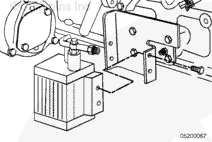
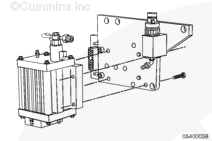
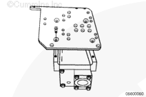
Install the Centinel™ oil control valve on the mounting bracket using the two M10-1.5 x 60 hex flange head capscrews. The capscrews insert through the two valve body mounting holes. Position the valve with the solenoid toward the front of the engine and the make-up line inlet toward the rear of the engine. Tighten the two capscrews.
Hello, I'm Jack, a diesel engine fan and a blogger. I write about how to fix and improve diesel engines, from cars to trucks to generators. I also review the newest models and innovations in the diesel market. If you are interested in learning more about diesel engines, check out my blog and leave your feedback.
View all posts by Jack

 WARNING




 CAUTION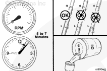




;)
;)
;)
;)
;)
;)
;)
;)
;)
;)
;)
;)
;)
;)
;)
;)
;)
;)
;)
;)
;)
;)
;)
;)
;)
;)
;)
;)
;)
;)
;)
;)
;)
;)
;)
;)
;)
;)
