|
Centinel™ Control Module Calibration Plug Malfunctioning
|

Overview
| CODE | REASON | EFFECT |
| Fault Code: 342 PID: FMI: LAMP: SRT: |
Centinel™ Control Module Calibration Plug Malfunctioning Heavy-Duty: no calibration plug installed. High-Horsepower: |
The Centinel™ system will not operate properly. |
|
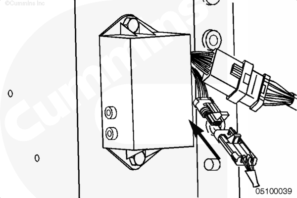
Calibration Plug |
 |
;)
;)
Circuit Description
The calibration plug is necessary for heavy-duty engines.
Component Location
Heavy-Duty: The calibration plug is a 3-pin connector that is located on the Centinel™ control module.
High-Horsepower:
The service plug is a 3-pin connector in the wiring harness near the light box.
Cautions and Warnings
 CAUTION CAUTION To avoid pin and harness damage, use the following test leads when taking measurements: |
Troubleshooting Steps
| STEPS | SPECIFICATIONS | |
|---|---|---|
| STEP 1. | Check calibration plug. | |
| STEP 1A. Verify calibration plug is installed. | Install the calibration plug | |
| STEP 1B. Check for an open in the calibration plug. | Less than 10 ohms | |
| STEP 2. | Check the Centinel™ harness. | |
| STEP 2A. Check for an open circuit. | Less than 10 ohms | |
| STEP 2B. Check for a short circuit to ground. | More than 1k ohms | |
| STEP 3. | Clear the fault codes. | |
| STEP 3A. Disable the fault code. | Fault Code 342 inactive | |
Guided Step 1 – Check the calibration plug.
| Guided Step 1A – Verify calibration plug is installed. | |
|---|---|
Conditions
Action
|
|
| OK | NOT OK |
|
Calibration plug is installed on heavy-duty. Service plug is not installed on high-horsepower. |
Heavy-Duty: install the calibration plug High-Horsepower: remove the service plug. |
| Guided Step 1B – Check for an open in the calibration plug. | |
|---|---|
Conditions
Action
For general resistance measurement techniques, refer to the Resistance Measurements Using a Multimeter and Wiring Diagram, Procedure 019-360. |
|
| OK | NOT OK |
|
Less than 10 ohms |
Repair or replace the calibration plug |
Guided Step 2 – Check the Centinel™ wiring harness.
|
CAUTION To avoid pin and harness damage, use the following test leads when taking measurements: |
| Guided Step 2A – Check for an open circuit. | |
|---|---|
ConditionsHeavy-Duty only:
Action
Refer to the wiring diagram for connector pin identification. For general resistance measurement techniques, refer to the Resistance Measurements Using a Multimeter and Wiring Diagram, Procedure 019-360. |
|
| OK | NOT OK |
|
Less than 10 ohms |
Replace the Centinel™ control module. Refer to Procedure 019-130. |
|
CAUTION To avoid pin and harness damage, use the following test leads when taking measurements: |
| Guided Step 2B – Check for a short circuit to ground. | |
|---|---|
ConditionsHeavy-duty only:
Action
Refer to the wiring diagram for connector pin identification. For general resistance measurement techniques, refer to the Resistance Measurements Using a Multimeter and Wiring Diagram, Procedure 019-360. |
|
| OK | NOT OK |
|
More than 1k ohms |
Replace the Centinel™ wiring harness Refer to Procedure 019-131. |
Guided Step 3 – Clear the fault codes.
| Guided Step 3A – Disable the fault code. | |
|---|---|
Conditions
Action
|
|
| OK | NOT OK |
|
Fault Code 342 inactive |
Return to troubleshooting steps or contact your local Cummins Authorized Repair Location if all the steps have been completed and checked again. |