|
J1587 Datalink Time-Out
|

Overview
| CODE | REASON | EFFECT |
| Fault Code: 414 PID: FMI: LAMP: SRT: |
J1587 Datalink Time-Out. The data was not received by the Centinel™ control module within the specified time. |
The Centinel™ system will not monitor engine dynamics and can not operate. |
|
J1587 Datalink |
 |
;)
;)
Circuit Description
The J1587 datalink provides communications capability between the parent engine electronic control module (ECM) and the Centinel™ control module. This allows the Centinel™ system the ability to monitor engine dynamics. Using these data, the Centinel™ system is able to function within the specified parameters.
Shop Talk
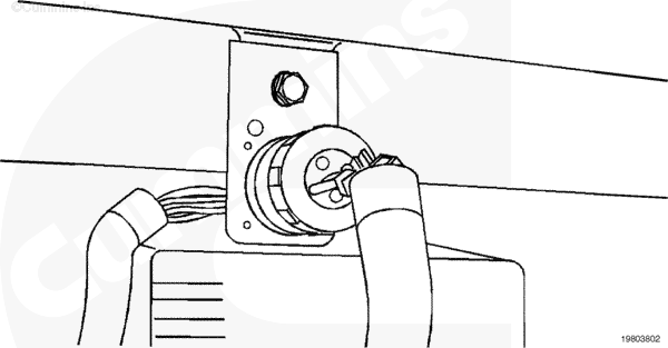
Before proceeding with this fault code, make certain that the Centinel™
wiring harness connector is securely connected to the J1587 datalink.
Cautions and Warnings
 CAUTION CAUTION To avoid pin and harness damage, use the following test leads when taking measurements: |
|
CAUTION To avoid pin and harness damage, use the following test leads when taking measurements: |
Troubleshooting Steps
| STEPS | SPECIFICATIONS | |
|---|---|---|
| STEP 1. | Check the datalink. | |
| STEP 1A. Inspect datalink connector. | No damaged pins | |
| STEP 2. | Check the Centinel™ wiring harness. | |
| STEP 2A. Check for reversed wires. | Pin A: 4 VDC; Pin B: 1 VDC | |
| STEP 2B. Inspect Centinel™ control module connector pins. | No damaged pins | |
| STEP 2C. Check for short circuit. | More than 1k ohms | |
| STEP 3. | Clear the fault code. | |
| STEP 3A. Disable fault code. | Fault Code 414 inactive | |
Guided Step 1 – Check data link.
| Guided Step 1A – Inspect datalink connector. | |
|---|---|
Conditions
Action
For general inspection techniques, refer to Component Connector and Pin Inspection, Procedure 019-361. |
|
| OK | NOT OK |
|
No damaged pins |
Repair damaged pins Repair or replace the control datalink connector. |
Guided Step 2 – Check the Centinel™ wiring harness.
|
CAUTION To avoid pin and harness damage, use the following test leads when taking measurements: |
| Guided Step 2A – Check for reversed wires. | |
|---|---|
Conditions
Action
Refer to the wiring diagram for connector pin identification. |
|
| OK | NOT OK |
|
Pin 8 to pin 2: Approximately 4 VDC; Pin 9 to pin 2: Approximately 1 VDC |
If voltages are opposite of specification, reverse the wires |
| Guided Step 2B – Inspect the Centinel™ wiring harness and Centinel™ control module connectors. | |
|---|---|
Conditions
Action
For general inspection techniques, refer to Component Connector and Pin Inspection, Procedure 019-361. |
|
| OK | NOT OK |
|
No damaged pins |
Repair the damaged pins Repair or replace the Centinel™ wiring harness or Centinel™ control module, whichever has the damaged pins. |
|
CAUTION To avoid pin and harness damage, use the following test leads when taking measurements: |
| Guided Step 2C – Check for a short circuit from pin to pin. | |
|---|---|
Conditions
Action
Refer to the wiring diagram for connector pin identification. For general resistance measurement techniques, refer to the Resistance Measurements Using a Multimeter and Wiring Diagram, Procedure 019-360. |
|
| OK | NOT OK |
|
More than 1k ohms |
Replace the Centinel™ control module Refer to Procedure 019-130. |
Guided Step 3 – Clear the fault code.
| Guided Step 3A – Disable the fault code. | |
|---|---|
Conditions
ActionVerify Fault Code 414 is inactive. |
|
| OK | NOT OK |
|
Fault Code 414 inactive |
Return to troubleshooting steps or contact your local Cummins Authorized Repair Location if all steps have been completed and rechecked. |