Centinel System – Repair Manual – 011-025   EGR Connection Tubes

Preparatory Steps

TOC

Automotive with CM870


 WARNING 

Wear safety glasses or a face shield, as well as protective clothing, to reduce the possibility of personal injury when using a steam cleaner or high-pressure water.
 WARNING 

The differential pressure sensor tube can be hot. To reduce the possibility of personal injury, allow the engine to cool before removing.

SMALL | MEDIUM | LARGE

Automotive With CM871


 WARNING 

Wear safety glasses or a face shield, as well as protective clothing, to reduce the possibility of personal injury when using a steam cleaner or high-pressure water.
 WARNING 

The differential pressure sensor tube can be hot. To reduce the possibility of personal injury, allow the engine to cool before removing.

NOTE: Brush away all loose dirt from around the area of the air handling connections to prevent contamination of the interior of the engine.

  • Use steam or high-pressure water to clean the engine, specifically around the EGR connection tube joints.
  • Remove the engine wiring harness from the exhaust temperature sensor. See the following procedure in the Troubleshooting and Repair Manual, CM871 and CM876 Electronic Control System, ISX and ISM Engines, Bulletin 4021560. Refer to Procedure 019-043 in Section 19.
  • Remove the EGR differential pressure sensing tubes from the EGR venturi. Refer to Procedure 011-026 in Section 11.

SMALL | MEDIUM | LARGE
   

Remove

TOC

Automotive with CM870


 WARNING 

The EGR connection tubes can be hot. To reduce the possibility of personal injury, allow the engine to cool before removing.

Loosen all hose clamps on the EGR connection tubes and remove the two p-clip mounting capscrews or nuts (depending on the vintage of the engine) on the front EGR connection tube.

If the M10 stud comes out upon removal of the nut, install the M10 stud into the block until the stud bottoms out.

Remove the one capscrew and one nut or the two nuts that attach the rear section of the connection tube to the cylinder block.

If the M10 stud comes out upon removal of the nut, install the M10 stud into the block until the stud bottoms out.

Remove the front EGR connection tube.

SMALL | MEDIUM | LARGE


Remove the one capscrew and one nut that attach the rear section of the connection tube to the cylinder block.

Remove the rear EGR connection tube from the EGR cooler.

SMALL | MEDIUM | LARGE
   

Automotive With CM871


 WARNING 

The EGR connection tubes can be hot. To reduce the possibility of personal injury, allow the engine to cool before removing.

Loosen the hose clamps on the front EGR connection tube and remove the hose.

Remove the two retaining capscrews on the lower portion of the tube at the EGR valve housing outlet.

Remove the front EGR connection tube and hose.

Discard the hose.

SMALL | MEDIUM | LARGE


Use protective caps from the Air Handling Clean Care Kit, Part Number 4919403 and Part Number 4919425, to cover the open points on all components.

 
SMALL | MEDIUM | LARGE


Remove the three EGR venturi mounting capscrews.

Remove the EGR venturi.

SMALL | MEDIUM | LARGE


Cover the irregular openings on the venturi and air intake connections with protective caps from the Air Handling Clean Care Kit, Part Number 4919403 and Part Number 4919425.

 
SMALL | MEDIUM | LARGE


Remove the two rear EGR connection capscrews from the EGR cooler.

Loosen the hose clamp on the rear EGR connection tube.

Pull the EGR cooler outlet connection tube from the EGR cooler.

SMALL | MEDIUM | LARGE


Use protective caps from the Air Handling Clean Care Kit, Part Number 4919403 and Part Number 4919425, to cover the open points on all components.

 
SMALL | MEDIUM | LARGE
   

Clean and Inspect for Reuse

TOC

Automotive with CM870


 WARNING 

When using solvents, acids, or alkaline materials for cleaning, follow the manufacturer’s recommendations for use. Wear goggles and protective clothing to reduce the possibility of personal injury.
 WARNING 

Wear appropriate eye and face protection when using compressed air. Flying debris and dirt can cause personal injury.

Clean the connection tubes with solvent.

Dry with compressed air.

Inspect the ends and mating joints of the connection tubes for cracks or other damage. Replace the tube if cracks or other damage is found.

SMALL | MEDIUM | LARGE


Inspect the p-clips for missing or torn rubber sleeves.

Replace the p-clips if the rubber sleeve is missing or torn.

SMALL | MEDIUM | LARGE


Inspect the band section of the clamp(s) for cracks or other damage.

Inspect the threaded section of the clamps for cracks or other damage.

Replace clamp(s) if cracks or other damage is present.

 
SMALL | MEDIUM | LARGE
   

Automotive With CM871


 WARNING 

When using solvents, acids, or alkaline materials for cleaning, follow the manufacturer’s recommendations for use. Wear goggles and protective clothing to reduce the possibility of personal injury.
 WARNING 

Wear appropriate eye and face protection when using compressed air. Flying debris and dirt can cause personal injury.

Clean the connection tubes with solvent.

Make sure that gasket sealing surfaces at the EGR valve outlet and EGR cooler outlet are free of packed soot and other debris. Avoid wiping dirt or debris down into the tubes or valve.

Dry with compressed air.

SMALL | MEDIUM | LARGE


Inspect the EGR measurement venturi for soot plugging at the EGR differential pressure sensing tube ports. The port labeled R has a hook inside that makes visual inspection difficult.

Insert a flexible pipe cleaner or wire through this port to verify the port is not plugged inside the tube, past the bend.

SMALL | MEDIUM | LARGE


Inspect the band section of the clamp(s) for cracks or other damage.

Inspect the threaded section of the clamps for cracks or other damage.

Replace the clamp(s) if cracks or other damage is present.

 
SMALL | MEDIUM | LARGE


Inspect the ends and mating joints of the connection tubes for signs of fretting, or material transfer, cracks, or other damage.

Replace the tube if fretting, material transfer, cracks, or other damage is found.

Inspect the rear EGR connection hose for cracks, fraying, or tearing.

Replace the entire rear EGR crossover tube if the hose is damaged or if hose material is found on the EGR valve mounting bracket.

SMALL | MEDIUM | LARGE
   

Install

TOC

Automotive with CM870


Use protective caps from the Air Handling Clean Care Kit, Part Number 4919403 and Part Number 4919425, at the end of the rear EGR connection tube that interfaces with the EGR cooler before working the tube into position, to reduce the possibility of introducing dirt or debris.

Install the p-clips onto the rear EGR connection tube.

Make sure the tube insulation is properly and fully located under the p-clips and that the p-clip rubber sleeve does not block the mounting hole.

Install the rear EGR connection tube and the p-clip mounting capscrew and nuts.

Hand-tighten the capscrew and nuts.

SMALL | MEDIUM | LARGE


Remove the protective caps from the component.

Install a new hose with the hose clamps loosely attached between the rear EGR connection tube and the EGR cooler.

Tighten the p-clip mounting capscrews, nuts, and hose clamps.

Torque Value:

M10 P-clip nut  46  n.m  [34 ft-lb]
Torque Value:

M8 P-clip nut  23  n.m  [204 in-lb]
Torque Value:

P-clip capscrew and nut  45  n.m  [33 ft-lb]
Torque Value:

Breeze Clamp (1)  7  n.m  [62 in-lb]
Torque Value:

Norma Clamp (2)  5  n.m  [44 in-lb]

SMALL | MEDIUM | LARGE


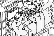
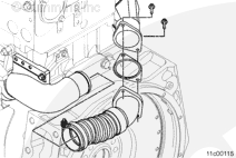
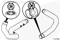
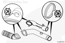
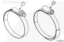
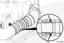
Install a new hose with the hose clamps loosely attached on the rear EGR connection tube where it interfaces with the front EGR connection tube.

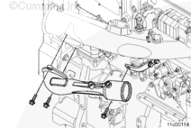
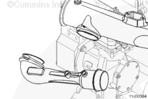
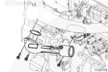
Install the p-clips onto the front EGR connection tube.

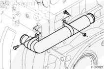
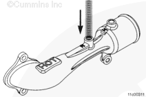
Install the front EGR connection tube and the p-clip mounting capscrews or nuts. Finger tighten the capscrews or nuts.

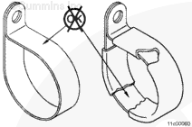
Tighten the p-clip mounting capscrews or nuts and the hose clamps.

Torque Value:

M10 p-clip nut  46  n.m  [34 ft-lb]
Torque Value:

Hose clamps  5  n.m  [44 in-lb]
Torque Value:

P-clip capscrew and nut  45  n.m  [33 ft-lb]

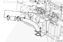
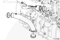
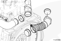
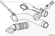
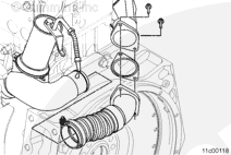
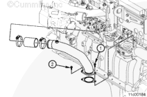
Install a new hose with the hose clamps loosely attached between the front EGR connection tube and the EGR mixer.

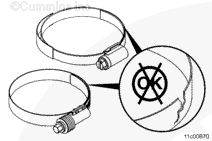
Tighten the p-clip mounting capscrews, nuts, and clamps.

Torque Value:

P-clip capscrews and nut  45  n.m  [33 ft-lb]
Torque Value:

Hose clamps  5  n.m  [44 in-lb]

SMALL | MEDIUM | LARGE
   

Automotive With CM871


Remove the protective caps from the component.

Apply lubricant to the hose end of the rear EGR connection tube.

Loosely install the hose clamp and install the rear EGR connection tube and gasket onto the EGR cooler and EGR valve mounting bracket.

Tighten the two capscrews.

Torque Value:  27  n.m  [239 in-lb]

SMALL | MEDIUM | LARGE


Make sure the indentation near the end of the hose slides past the hose bead on the EGR valve mounting bracket. Position the hose clamp on this indentation groove.

Tighten the hose clamp.

Torque Value:  7  n.m  [62 in-lb]

NOTE: Install the protective sleeve onto the exposed threads of a T-bolt style clamp.

NOTE: Two different types of hose clamps can be used in this location. The torque value for each clamp is the same, regardless of which clamp is used.

 
SMALL | MEDIUM | LARGE


Loosen the two rear tail support mounting capscrews.

Install a new press-in place seal on the EGR venturi.

Install the EGR venturi on the air intake connection by loosely installing all three capscrews. Hand-tighten all five capscrews.

In order to reduce assembly stress, tighten the capscrews in the following sequence:

Tighten the two front EGR venturi mounting capscrews.

Torque Value:  47  n.m  [35 ft-lb]

Tighten the rear EGR venturi mounting capscrews.

Torque Value:  47  n.m  [35 ft-lb]

Tighten the two rear tail support mounting capscrews.

Torque Value:  47  n.m  [35 ft-lb]

SMALL | MEDIUM | LARGE


Apply lubricant to the hose end of the front EGR connection tube and the EGR venturi inlet.

Slide the new EGR connection hose on the EGR venturi inlet and loosely install both retaining clamps.

Attach a new EGR gasket to the front EGR connection tube flange, holding it in place with the two retaining capscrews.

Insert the hose end of the EGR connection tube into the EGR connection hose, and align the mounting flange with the EGR valve outlet.

Install the two retaining capscrews into the EGR valve.

Tighten the capscrews in the following sequence: Capscrew 1, Capscrew2, Capscrew 1.

Make sure to tighten Capscrew 1 twice.

Torque Value:  27  n.m  [239 in-lb]

Center the EGR connection hose evenly between the tube and the EGR venturi and tighten both retaining clamps.

Torque Value:  7  n.m  [62 in-lb]

NOTE: Two different types of hose clamps can be used in this location. The torque value for each clamp is the same, regardless of which clamp is used.

SMALL | MEDIUM | LARGE
   

Finishing Steps

TOC

Automotive with CM870


 WARNING 

Wear safety glasses or a face shield, as well as protective clothing, to reduce the possibility of personal injury when using a steam cleaner or high-pressure water.
 WARNING 

The differential pressure sensor tube can be hot. To reduce the possibility of personal injury, allow the engine to cool before removing.

SMALL | MEDIUM | LARGE
   

Automotive With CM871


 WARNING 

Wear safety glasses or a face shield, as well as protective clothing, to reduce the possibility of personal injury when using a steam cleaner or high-pressure water.
 WARNING 

The differential pressure sensor tube can be hot. To reduce the possibility of personal injury, allow the engine to cool before removing.
  • Install the EGR differential pressure sensing tubes to the EGR venturi. Refer to Procedure 011-026 in Section 11.
  • Install the engine wiring harness to the exhaust temperature sensor. Use the following procedure in the Troubleshooting and Repair Manual CM871 and CM876 Electronic Control System ISX and ISM Engines, Bulletin 4021560. Refer to Procedure 019-043 in Section 19.
  • Operate the engine and check for leaks.

SMALL | MEDIUM | LARGE
Last Modified:  11-Oct-2010