The catalyst elements contained in the aftertreatment system are made of brittle material. Do not drop or strike the side of the aftertreatment system, as damage to the catalyst element can result.
Due to the number of exhaust aftertreatment applications, this procedure is generic. Not all illustrations within the procedure will represent all applications.
The exhaust aftertreatment system is composed for four sections. These sections are:
Inlet
Aftertreatment Diesel Oxidation Catalyst
Aftertreatment Diesel Particulate Filter
Outlet
NOTE: In some applications, the catalyst can be integrated into the inlet of the exhaust aftertreatment.
NOTE: On some vertically oriented aftertreatment systems, the differential pressure sensor mounting bracket may be welded to the outlet section of the aftertreatment system. The outlet section of this type of aftertreatment system must be replaced if the differential pressure sensor mounting bracket is damaged.
Batteries can emit explosive gases. To reduce the possibility of personal injury, always ventilate the compartment before servicing the batteries. To reduce the possibility of arcing, remove the negative (-) battery cable first and attach the negative (-) battery cable last.
CAUTION
The aftertreatment diesel particulate filter and catalyst can remain hot for long periods of time after the engine has stopped.
Disconnect the batteries. Refer to the OEM service manual.
Disconnect the aftertreatment wiring harness from the aftertreatment diesel particulate filter differential pressure sensor. Refer to Procedure 019-443 in Section 19. This procedure can be located in the Troubleshooting and Repair CM871 and CM876 Electronic Control System ISX and ISM Engines, Bulletin 4021560.
Remove the aftertreatment diesel particulate filter differential pressure sensor. Refer to Procedure 019-376 in Section 19. This procedure can be located in the Troubleshooting and Repair CM871 and CM876 Electronic Control System ISX and ISM Engines, Bulletin 4021560.
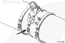
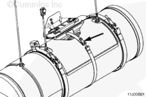
Mark the orientation and location of the bracket before it is removed, to aid installation if there is not a locating tab present.
Remove the nut on the aftertreatment diesel particulate filter differential pressure sensor mounting bracket strap.
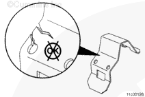
NOTE: A cylindrical locating tab may be welded to the outside of the catalyst canister to position the differential pressure sensor mounting bracket. Note the orientation of the mounting bracket prior to removal.
NOTE: Remove the differential pressure sensor mounting bracket and strap.
The aftertreatment system must be installed so the aftertreatment diesel particulate filter differential pressure sensor tubes slope downward to drain condensation away from the differential pressure sensor.
NOTE: A cylindrical locating tab may be welded to the outside of the catalyst canister to position the differential pressure sensor mounting bracket.
NOTE: Make sure the aftertreatment system is oriented so the aftertreatment diesel particulate filter differential pressure sensor is installed in the same orientation noted during disassembly.
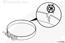
Install the differential pressure sensor mounting bracket and strap. Be sure to align the cylindrical locating tab, if present, with the mounting bracket, as noted during removal.
If there is not a locating tab, use the reference mark that was made during removal.
Apply a coating of anti-seize compound to the threads of the aftertreatment diesel particulate filter differential pressure sensor mounting bracket strap.
Install the nut on the aftertreatment diesel particulate filter differential pressure sensor mounting bracket strap.
Tighten the differential pressure sensor mounting bracket strap.
Batteries can emit explosive gases. To reduce the possibility of personal injury, always ventilate the compartment before servicing the batteries. To reduce the possibility of arcing, remove the negative (-) battery cable first and attach the negative (-) battery cable last.
Install the aftertreatment diesel particulate filter differential pressure sensor. Refer to Procedure 019-376 in Section 19. This procedure can be located in the Troubleshooting and Repair CM871 and CM876 Electronic Control System ISX and ISM Engines, Bulletin 4021560.
Connect the aftertreatment wiring harness from the aftertreatment diesel particulate filter differential pressure sensor. Refer to Procedure 019-443 in Section 19. This procedure can be located in the Troubleshooting and Repair CM871 and CM876 Electronic Control System ISX and ISM Engines, Bulletin 4021560.
Connect the batteries. Refer to the OEM service manual.
Operate the engine and check for proper operation.
Hello, I'm Jack, a diesel engine fan and a blogger. I write about how to fix and improve diesel engines, from cars to trucks to generators. I also review the newest models and innovations in the diesel market. If you are interested in learning more about diesel engines, check out my blog and leave your feedback.
View all posts by Jack
 CAUTION
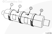
 WARNING


;)
;)
;)
;)
;)
;)
;)
;)
;)
;)
;)
;)