ISM, ISMe, and QSM11 – 011-047   Aftertreatment Diesel Particulate Filter Differential Pressure Sensor Tubes

General Information

TOC

The aftertreatment diesel particulate filter differential pressure sensor tubes connect the differential pressure sensor to the ports on the aftertreatment system. There are two aftertreatment diesel particulate filter differential pressure sensor tubes. One tube connects to the aftertreatment system upstream of the aftertreatment diesel particulate filter and the other connects downstream of the aftertreatment diesel particulate filter.

Due to the number of exhaust gas aftertreatment configurations, this procedure is generic. Not all illustrations within this procedure will represent all applications.

Carbon deposits inside the tubes can cause an amber CHECK ENGINE light.

 
SMALL | MEDIUM | LARGE

Remove

TOC

 CAUTION 

The aftertreatment diesel particulate filter differential pressure sensor will not operate properly if the differential pressure sensor tubes are not connected to the correct port. Mark the differential pressure sensor tube connection port locations before disconnecting.
 CAUTION 

If the flexible hose section between the differential pressure sensor tube and the differential pressure sensor are difficult to remove, cut and replace the hose. Twisting or bending the hose can damage the pressure sensor.

NOTE: The mounting location of the aftertreatment diesel particulate filter differential pressure sensor varies with exhaust aftertreatment orientation and OEM mounting location.

Remove the spring clamps from the stainless steel tube end of the flexible hose sections attached to the exhaust gas filter pressure sensor.

Loosen the aftertreatment diesel particulate filter differential pressure sensor tube nuts.

If p-clips or tube clamps are used to hold the exhaust gas filter pressure sensor tubes on the exhaust aftertreatment system, mark their location prior to removal.

Remove the p-clips or tube clamp mounting capscrews, if necessary.

SMALL | MEDIUM | LARGE
   

Clean and Inspect for Reuse

TOC

 WARNING 

When using solvents, acids, or alkaline materials for cleaning, follow the manufacturer’s recommendations for use. Wear goggles and protective clothing to reduce the possibility of personal injury.
 WARNING 

Wear appropriate eye and face protection when using compressed air. Flying debris and dirt can cause personal injury.

Inspect the inside of the tube.

If the tube is partially clogged, saturate the inside of the tube with a mineral based solvent, or equivalent.

Carefully clean debris from the mouth of the tubes, make sure not to damage the tube.

If the tube is fully clogged or otherwise unable to be cleaned, the tube must be replaced.

Clean the tube with safety solvent.

Dry the tube with compressed air.

Check the tube for cracks and thread damage. Replace the tube, if damage is found.

SMALL | MEDIUM | LARGE


Inspect the inside of the threaded bosses on the aftertreatment canister.

Clean debris from the inside of the threaded bosses, while being careful to not damage the threads.

SMALL | MEDIUM | LARGE
   

Install

TOC

 CAUTION 

The aftertreatment diesel particulate filter differential pressure sensor will not operate properly if the differential pressure sensor tubes are not connected to the correct port. Install the differential pressure sensor tubes as noted during disassembly.
 CAUTION 

The aftertreatment system must be installed so the aftertreatment diesel particulate filter differential pressure sensor tubes slope downward to drain condensation away from the differential pressure sensor.

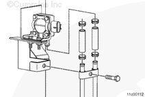
The aftertreatment diesel particulate filter differential pressure sensor port closest to the sensor mounting bracket connects upstream of the aftertreatment diesel particulate filter.

NOTE: In vertical aftertreatment orientations, an aftertreatment diesel particulate filter differential pressure sensor tube support can be present. Be sure the differential pressure tubes are seated in the support clip.

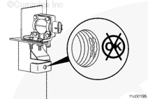
Apply a coating of Locite™ 80209, 51002, 76732, copper or silver grade, or equivalent to the threads on the differential pressure sensor tubes prior to assembly. Do not allow Loctite™ to enter inside of the differential pressure sensor tubes. This can cause a blockage.

Minimum Loctite™ Anti-Seize Temperature Range

celsius fahrenheit
870° MIN 1600°

Install the differential pressure sensor tubes on the aftertreatment system.

Attach the flexible hose sections of the differential pressure sensor tubes to the differential pressure sensor using two spring clamps.

NOTE: Make sure the differential pressure sensor tubes are not making contact with each other or any other vehicle components prior to tightening the differential pressure sensor tube nuts.

NOTE: Tighten the aftertreatment diesel particulate filter differential pressure sensor tube nuts.

Torque Value:  17  n.m  [150 in-lb]

Install the p-clips or the tube clamps that hold the exhaust gas filter pressure sensor tubes on the exhaust aftertreatment system.

Tighten the p-clips or the tube clamp bolts, if necessary.

Torque Value:  14  n.m  [124 in-lb]

Operate the vehicle on a dynamometer or perform a road test with the engine at rated load for a minimum of 5 minutes to make sure the aftertreatment system is performing properly.

Check for fault codes and exhaust leaks.

SMALL | MEDIUM | LARGE
Last Modified:  09-Jun-2010