During regeneration, exhaust gas temperature could reach 800°C [1500°F], and exhaust system surface temperature could exceed 700°C [1300°F], which is hot enough to ignite or melt common materials, and to burn people. The exhaust and exhaust components can remain hot after the vehicle has stopped moving. To avoid the risk of fire, property damage, burns or other serious personal injury, allow the exhaust system to cool before beginning this procedure or repair and make sure that no combustible materials are located where they are likely to come in contact with hot exhaust or exhaust components.
CAUTION
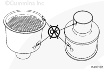
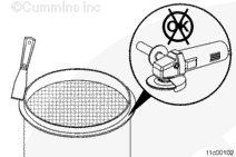
The catalyst elements contained in the aftertreatment system are made of brittle material. Do not drop or strike the side of the aftertreatment system as damage to the catalyst element can result.
Due to the number of various exhaust aftertreatment applications, this procedure has been written to be generic. Illustrations within this procedure will not represent all applications.
The aftertreatment system is composed of four sections. These sections are:
Inlet
Aftertreatment diesel oxidation catalyst
Aftertreatment diesel particulate filter
Outlet.
NOTE: In some applications, the catalyst can be integrated into the inlet of the exhaust aftertreatment system.
Batteries can emit explosive gases. To reduce the possibility of personal injury, always ventilate the compartment before servicing the batteries. To reduce the possibility of arcing, remove the negative (-) battery cable first and attach the negative (-) battery cable last.
CAUTION
The aftertreatment diesel particulate filter differential pressure sensor will not operate properly if the differential pressure sensor tubes are not connected to the correct port. Mark the differential pressure sensor tube connection locations before disconnecting.
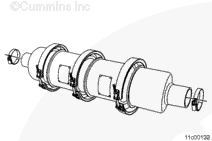
Mark the direction of exhaust flow to aid in assembly.
Draw an orientation reference line across each of the v-band clamps, aftertreatment canister sections, and connection points to the tailpipe. This will aid in returning the sections and the v-band clamps to their original orientation during installation.
Mark the number of each exhaust gas temperature sensor connector prior to disconnecting the exhaust temperature sensor from the wiring harness.
This component or assembly weighs greater than 23 kg [50 lb]. To prevent serious personal injury, be sure to have assistance or use appropriate lifting equipment to lift this component or assembly.
CAUTION
The catalyst elements contained in the aftertreatment system are made of brittle material. Do not drop or strike the side of the aftertreatment system as damage to the catalyst element can result.
Inspect the aftertreatment inlet and outlet canisters for cracks or other damage.
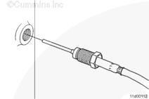
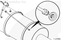
Inspect the aftertreatment gas temperature sensor boss threads for damage, if the sensor was removed.
Inspect the aftertreatment diesel particulate filter differential pressure sensor tube boss threads for damage, if the tube was removed.
If thread damage is found on the aftertreatment gas temperature sensor boss threads or differential pressure sensor tube boss threads, a helicoil must be used for repair.
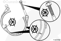
Apply a coat of anti-seize compound on the treads of the v-band clamps and Torca™ clamps.
The aftertreatment outlet section contains a differential pressure sensor tube boss. Align the differential pressure sensor tube boss with the differential pressure sensor tube nut prior to tightening the v-band clamp or the Torca™
clamp.
NOTE: If the Torca™ clamp is replaced during service, be sure to replace it with another Torca™ clamp. Do not use a u-bolt as a replacement clamp. U-bolt clamps can crush the tailpipe and make it difficult to remove the aftertreatment system for future service.
Batteries can emit explosive gases. To reduce the possibility of personal injury, always ventilate the compartment before servicing the batteries. To reduce the possibility of arcing, remove the negative (-) battery cable first and attach the negative (-) battery cable last.
CAUTION
If the temperature sensor wire connectors are not connected to the proper locations after installation, aftertreatment system damage can result.
CAUTION
The aftertreatment diesel particulate filter differential pressure sensor will not operate properly if the differential pressure sensor tubes are not connected to the correct port. Install the differential pressure sensor tubes as noted during disassembly.
Install the mounting straps or bolts to the inlet, if necessary. Refer to the OEM troubleshooting and repair manual.
Install the mounting straps or bolts from the outlet, if necessary. Refer to the OEM troubleshooting and repair manual.
Hello, I'm Jack, a diesel engine fan and a blogger. I write about how to fix and improve diesel engines, from cars to trucks to generators. I also review the newest models and innovations in the diesel market. If you are interested in learning more about diesel engines, check out my blog and leave your feedback.
View all posts by Jack
 WARNING
  CAUTION
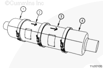


;)
;)
;)
;)
;)
;)
;)
;)
;)
;)
;)
;)
;)
;)
;)
;)