The catalyst elements contained in the aftertreatment system are made of brittle material. Do not drop or strike the side of the aftertreatment system as damage to the catalyst element can result.
Due to number of exhaust aftertreatment applications, this procedure is generic. Illustrations within this procedure will not represent all applications.
The exhaust aftertreatment is composed of four sections. These sections are:
Inlet
Aftertreatment diesel oxidation catalyst
Aftertreatment diesel particulate filter
Outlet.
NOTE: In some applications the catalyst can be integrated into the inlet of the exhaust aftertreatment.
Batteries can emit explosive gases. To reduce the possibility of personal injury, always ventilate the compartment before servicing the batteries. To reduce the possibility of arching, remove the negative (-) battery cable first and attach the negative (-) batter cable last.
CAUTION
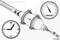
The catalyst can remain hot for a long time after the engine has stopped.
Disconnect the batteries. Refer to the OEM service manual.
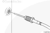
Disconnect the aftertreatment exhaust gas temperature sensor electrical connector(s) from the wiring harness, if necessary. Refer to Procedure 019-449 in Section 19. This procedure can be located in the Troubleshooting and Repair Manual, ISX and ISM Engines, Bulletin 4021560.
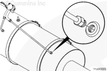
Disconnect the aftertreatment diesel particulate filter differential pressure sensor mounting bracket, and strap if applicable. Refer to Procedure 011-046 in Section 11.
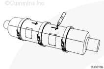
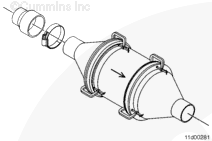
Draw an orientation reference line across each of the v-band clamps, aftertreatment canister sections, and connection points to the tailpipe. This will aid in returning the sections and v-band clamps to their original orientation during installation.
Mark the direction of exhaust flow on both the catalyst section and the aftertreatment diesel particulate filter section to aid in assembly.
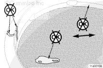
The component weighs 23 kg [50 lbs] or more. To reduce the possibility of personal injury, use a hoist or get assistance to lift the component.
CAUTION
The catalyst elements contained in the aftertreatment system are made of brittle material. Do not drop or strike the side of the aftertreatment system as damage to the catalyst element can result.
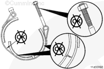
CAUTION
Do not use air tools to remove or install the nut on the v-band clamp. Use of these tools can seriously damage the threads or the bolt and cause the camp to not be reusable.
NOTE: If necessary, remove additional mounting hardware to remove the catalyst from the vehicle.
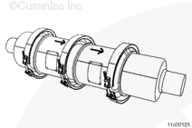
Remove the v-band clamps from the inlet and outlet of the catalyst.
Separate the component sections by approximately one-half inch to allow removal over the gasket retainer rings.
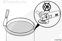
Do not use a grinder or abrasive air tool to remove residual gasket material, as this can damage the flange and cause the connection to leak.
CAUTION
Do not use an open flame to burn off soot accumulation from the face of the aftertreatment diesel particulate filter.
CAUTION
Do not scrape off soot accumulation from the face of the aftertreatment diesel particulate filter.
Remove any residual gasket material from the flanges on the aftertreatment diesel particulate filter with a putty knife.
Avoid dropping fragments of gasket material into the aftertreatment diesel particulate filter.
NOTE: If the aftertreatment diesel particulate filter is being inspected due to progressive damage that introduced engine oil or excessive fuel into the exhaust, inspect the tailpipe from the turbocharger outlet to the aftertreatment diesel oxidation catalyst.
If a trail of liquid engine oil or fuel can be seen from the turbocharger outlet to the aftertreatment diesel oxidation catalyst, the aftertreatment diesel oxidation catalyst must be replaced.
If a trail of engine oil or fuel can be seen exiting the turbocharger outlet, the tailpipe between the turbocharger outlet and aftertreatment diesel oxidation catalyst must be cleaned. Refer to Procedure 011-048 in Section 11.
The material captured in a diesel particulate filter may contain elevated concentrations of metals, primarily zinc and molybdenum, and possibly polynuclear aromatic hydrocarbons that may be regulated. These materials must be characterized, handled, and disposed of according to applicable local regulations. In addition, due to the presence of the above-listed chemicals and other potentially toxic components such as oxides of calcium, zinc, phosphorous, silicone, sulfur, and iron, exhaust filter maintenance must be completed only by appropriately trained personnel.
WARNING
Wear appropriate eye and face protection when using compressed air. Flying debris and dirt can cause personal injury.
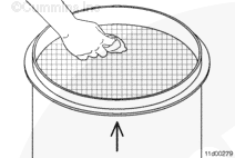
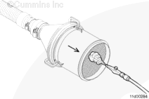
Inspect the outlet of the aftertreatment diesel oxidation catalyst for loose debris and soot. Use a rag to wipe off any soot. Use a HEPA vacuum to remove any remaining loose debris.
NOTE: Use a vacuum bag, such as a drywall dust bag, to capture the soot that is removed.
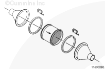
Attach the Cummins® aftertreatment diesel particulate filter cleaning machine cone, Part Number 4918850, to the inlet and outlet sides of the aftertreatment diesel oxidation catalyst with the adapter rings, Part Number 4918847 and 4918848. Evenly space 4 to 5 spring clamps or C-clamps around the circumference of the aftertreatment diesel oxidation catalyst to seal the cone and adapter ring to the aftertreatment diesel oxidation catalyst.
Service tool kit, Part Number 4918877 contains the cones and rings needed for this procedure.
If the aftertreatment diesel oxidation catalyst is integrated into the aftertreatment inlet, use one cone only, and attach it to the outlet side of the unit.
Obtain a 76 mm to 51 mm [3 in to 2 in] rubber pipe reducer from a local supplier. If the aftertreatment diesel oxidation catalyst is integrated into the aftertreatment inlet, obtain a 102 mm to 51 mm [4 in to 2 in] rubber pipe reducer.
Attach the vacuum hose to the 51 mm [2 in] end of the pipe reducer. Attach the larger end of the reducer to the aftertreatment diesel particulate filter cleaning machine cone attached to the inlet side of the diesel oxidation catalyst. If the aftertreatment diesel oxidation catalyst is integrated into the inlet, install the larger end of the reducer onto the aftertreatment inlet.
Use only a rubber-tipped air gun near the catalyst material. Damage will result if a metal air gun strikes the catalyst material.
Adjust the air supply for a rubber-tipped air gun to 621 kPa [90 psi].
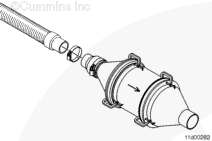
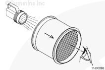
Switch on the vacuum. The vacuum and service tool kit is properly installed if the air flow through the aftertreatment diesel oxidation catalyst is opposite to exhaust flow. Exhaust flow is indicated by an arrow on the canister of the diesel oxidation catalyst.
Blow compressed air across the outlet face of the aftertreatment diesel oxidation catalyst for approximately 5 minutes.
After 5 minutes, remove the aftertreatment diesel particulate filter cleaning machine cone and continue blowing compressed air into the outlet of the diesel oxidation catalyst for an additional 10 to 15 minutes. Maintain a 13 mm to 25 mm [1/2 in to 1 in] distance between the air gun and diesel oxidation catalyst face. Use a sweeping motion across the entire face of the diesel oxidation catalyst and attempt to blow air through every cell.
Allow the vacuum to operate for 1 minute after blowing out the aftertreatment diesel oxidation catalyst. After the vacuum is switched off, disconnect the cleaning machine cone and inspect the cells of the diesel oxidation catalyst.
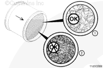
Inspect the cells of the diesel oxidation catalyst by looking through each cell. Shine a light on the opposite side of the diesel oxidation catalyst to aid inspection. If the cell is clear of soot, it is possible to see straight through the diesel oxidation catalyst.
Upon inspection, if less than 50 percent of the cells are blocked (1) the aftertreatment diesel oxidation catalyst can be reused. If more than 50 percent of the cells remain blocked (2), repeat the cleaning procedure.
NOTE: It should not take more than two attempts to clean the face of the DOC.
If the catalyst section has shifted, moved, or is loose inside the canister, replace the catalyst section.
Inspect the inlet and outlet faces of the aftertreatment diesel oxidation catalyst for signs of damage. Refer to Additional Aftertreatment Diesel Oxidation Catalyst and Aftertreatment Diesel Particulate Filter Reuse Guidelines, Bulletin 4021600.
Install the exhaust gas temperature sensor into the catalyst section, if necessary. Refer to Procedure 019-449 in Section 19. This procedure can be located in the Troubleshooting and Repair Manual, ISX and ISM Engines, Bulletin 4021560.
NOTE: If the engine had turbocharger damage or any other damage that introduced foreign objects into the exhaust system, the aftertreatment exhaust gas temperature 1 sensor must be inspected for damage. If the sensor is broken or damaged it must be replaced.
Batteries can emit explosive gases. To reduce the possibility of personal injury, always ventilate the compartment before servicing the batteries. To reduce the possibility of arching, remove the negative (-) battery cable first and attach the negative (-) batter cable last.
Connect the aftertreatment diesel particulate filter differential pressure sensor mounting bracket and strap if necessary. Refer to Procedure 011-046 in Section 11.
NOTE: If a malfunction resulted in oil, excessive fuel, or excessive black smoke entering the exhaust system, the aftertreatment system must be inspected. Refer to the Aftertreatment Diesel Oxidation Catalyst and Aftertreatment Diesel Particulate Filter Reuse Guidelines, Bulletin 4021600.
Hello, I'm Jack, a diesel engine fan and a blogger. I write about how to fix and improve diesel engines, from cars to trucks to generators. I also review the newest models and innovations in the diesel market. If you are interested in learning more about diesel engines, check out my blog and leave your feedback.
View all posts by Jack
 CAUTION
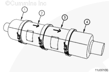
 WARNING


;)
;)
;)
;)
;)
;)
;)
;)
;)
;)
;)
;)
;)
;)
;)
;)
;)
;)
;)
;)
;)
;)
;)
;)
;)
;)
;)
;)
;)
;)
;)
;)
;)
;)