|
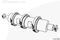
Inspect inlet or outlet canister. Refer to Procedure 011-048 in Section 11.
Inspect the aftertreatment diesel particulate filter canister. Refer to Procedure 011-041 in Section 11.
Inspect the catalyst canister. Refer to Procedure 011-049 in Section 11.
Inspect the exhaust gas temperature sensors. Refer to Procedure 019-449 in Section 19
This procedure is found in the Troubleshooting and Repair Manual, CM871 and CM876 Electronic Control System, ISX and ISM Engines, Bulletin 4021560.
Inspect the differential pressure sensor. Refer to Procedure 019-443 in Section 19.
This procedure is found in the Troubleshooting and Repair Manual, CM871 and CM876 Electronic Control System, ISX and ISM Engines, Bulletin 4021560.
Inspect the differential pressure sensor tubes. Refer to Procedure 011-047 in Section 19.
Inspect the aftertreatment system wire harness.
Inspect the Torca™ clamps and/or v-band clamps for leaks. Refer to Procedure 010-024 in Section 10.
This procedure is found in the Signature™, ISX, and QSX15 Service Manual, Bulletin 3666239.
Refer to Procedure 010-024 in Section 10.
This procedure is found in the ISM, ISMe, and QSM11 Service Manual, Bulletin 3666322.
|
 CAUTION
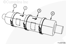
 WARNING


;)
;)
;)
;)
;)
;)