Batteries can emit explosive gases. To reduce the possibility of personal injury, always ventilate the compartment before servicing the batteries. To reduce the possibility of arcing, remove the negative (-) battery cable first and attach the negative (-) battery cable last.
WARNING
Coolant is toxic. Keep away from children and pets. If not reused, dispose of in accordance with local environmental regulations.
WARNING
Do not remove the pressure cap from a hot engine. Wait until the coolant temperature is below 50°C [120°F] before removing the pressure cap. Heated coolant spray or steam can cause personal injury.
WARNING
During regeneration, exhaust gas temperature could reach 800°C [1500°F], and exhaust system surface temperature could exceed 700°C [1300°F], which is hot enough to ignite or melt common materials, and to burn people. The exhaust and exhaust components can remain hot after the vehicle has stopped moving. To avoid the risk of fire, property damage, burns or other serious personal injury, allow the exhaust system to cool before beginning this procedure or repair and make sure that no combustible materials are located where they are likely to come in contact with hot exhaust or exhaust components.
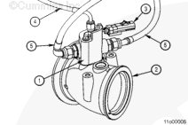
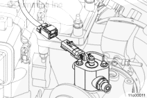
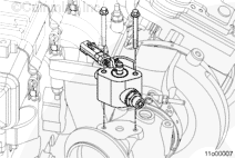
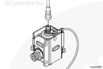
The aftertreatment fuel injector is used to inject diesel fuel into the exhaust flow prior to the intake of the DOC. The aftertreatment diesel injector is located on the aftertreatment exhaust pipe, mounted on a flange with two capscrews.
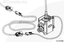
There are three primary connections at the aftertreatment fuel injector:
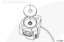
Aftertreatment fuel injector.
Aftertreatment exhaust pipe.
A 2-pin electrical connection, which connects the aftertreatment fuel injector to the wiring harness.
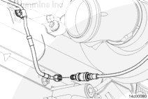
A diesel fluid supply line, which connects the aftertreatment injector to the aftertreatment fuel shutoff valve.
A coolant supply/return connection, which connects the aftertreatment fuel injector to the engine’s cooling system
Use the Coolant DAM™ or equivalent vacuum pump to prevent draining the cooling system when the aftertreatment injector coolant lines are disconnected.
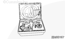
The Coolant DAM™, Part Number 3824319, uses shop air to retain and pressure test the coolant system eliminating the need to drain coolant system for minor repairs (block openings up to 19 mm [3/4 in] diameter).
Disconnect the vehicle batteries. Refer to the OEM service manual.
Remove the radiator cap.
Gather all necessary plugs and fittings such as radiator caps and block fittings
Determine the appropriate radiator/coolant expansion tank cap adapter for the vehicle being serviced. The available radiator caps and application can be found in Service Products Catalog Section 14. If your cap is not listed, it may be necessary to obtain and modify a replacement radiator cap from the OEM.
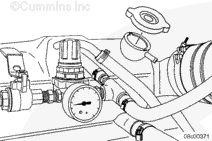
If using the “COOLANT DAM™” refer to procedure ST-3824319 Section 14 or if using equivalent vacuum pump follow the manufacturer’s installationand user manual.
Install service tool on the radiator neck, using appropriate adapter(s).
Apply a vacuum to the cooling system not to exceed radiator cap pressure.
It is necessary to disconnect each coolant line one at a time and install the correct plugs to minimize any unintended coolant loss. Failure to do so can cause damage to the coolant system.
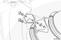
Insert cooling line plugs, Part Number 3089567 (ISX CM871 Only), at the engine block connection and Part Number 4918690 (ISX/ISM), into the bottom coolant line.
Torque Value: 24 n.m [212 in-lb]
Once coolant lines are plugged, the vacuum on the cooling system can be removed.
Do not connect a 12-VDC supply to the injector as this will cause permanent damage to the injector.
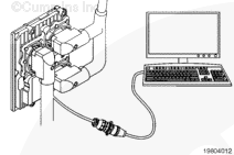
Connect the aftertreatment fuel injector electrical harness extension, Part Number 4918518, to the engine harness and the aftertreatment fuel injector.
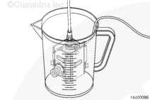
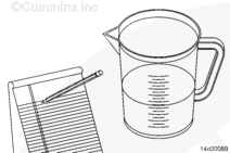
Obtain a clear graduated cylinder (large enough to hold the aftertreatment injector) that is marked in cubic centimeters; example: graduated beaker, Part Number 3823705, or equivalent. A measurement cup that is marked in milliliters (ml) or ounces (oz) can also be used.
The measuring device must be capable of measuring between 0 ml [0.0 oz] and 500 ml [17.0 oz] in 10 ml [0.34 oz] increments.
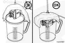
Place the aftertreatment fuel injector in the graduated cylinder or cup.
NOTE: It is usually easier to capture the fuel in a clean container and transfer the fuel to the measuring device for the final measurement.
Use INSITE™ electronic service tool to perform the aftertreatment “Reset All” function. This function can be found under the Advanced ECM Data, Aftertreatment Maintenance screen in INSITE™ electronic service tool.
NOTE: This test should only be performed after completing the “Reset All” as described above.
Start the engine and allow it to idle for 5 minutes.
Use INSITE™ electronic service tool to select System Test in the test mode section of the Aftertreatment Shutoff Valve and Injector Override Test.
Use INSITE™ electronic service tool to enter a time delay, if needed.
Click the Start button when ready to perform the test.
Click the OK button when the warning windows pop up, if the conditions are met.
INSITE™ electronic service tool will start the test and will inject fuel for 2 minutes and 30 seconds. INSITE™ electronic service tool will automatically disable the injector at the end of the test. If the test needs to be stopped before finishing, click the Stop button.
If the average amount collected is not within the specified limits, perform the flow test a second time.
Record the amount of fuel that was collected in the graduated cylinder during the 2 minutes and 30 seconds test period.
Perform the test 3 times and average the results of the three tests.
The average amount of fuel collected must be between 200 and 430 ml [6.8 and 14.5 oz].
If the average amount collected is not within this specification, check the part number of the aftertreatment fuel injector.
NOTE: The part number can be found by looking at the body of the fuel injector with the heat shield removed.
If it is Part Number 3683570, replace the aftertreatment fuel injector. If it is not Part Number 3683570, follow the following steps:
If the average amount collected is above the specified flow values, verify the INSITE™ electronic service tool “Reset All” function was completed and flow the doser again.
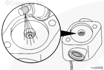
If the average amount collected is below the specification, make sure a brass brush was used to clean the tip and repeat the cleaning.
NOTE: A thorough 1 minute cleaing using the appropriate tools returns a low-flowing doser to within the specified flow values.
Use INSITE™ electronic service tool to select Injector Leak in the test mode section of the Aftertreatment Shutoff Valve and Injector Override Test.
Click the Start button to initiate the test.
Record the amount of fuel collected during the 1 minute INSITE™ electronic service tool test.
If more than 60 ml [2 oz] of fuel is collected during the 1 minute INSITE™ electronic service tool test, replace the aftertreatment fuel injector. Refer to Procedure 011-042 in Section 11.
Hello, I'm Jack, a diesel engine fan and a blogger. I write about how to fix and improve diesel engines, from cars to trucks to generators. I also review the newest models and innovations in the diesel market. If you are interested in learning more about diesel engines, check out my blog and leave your feedback.
View all posts by Jack
 WARNING


 CAUTION
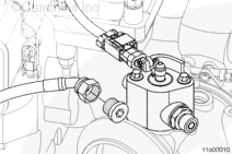


;)
;)
;)
;)
;)
;)
;)
;)
;)
;)
;)
;)
;)
;)
;)
;)
;)
;)
;)
;)
;)
;)
;)
;)
;)
;)
;)
;)
;)
;)
;)
;)
;)
;)