ISM, ISMe, and QSM11 – 001-014   Connecting Rod

Preparatory Steps

TOC

The piston and connecting rod must be removed as an assembly on M Series engines. Refer to Procedure 001-054 in Section 1.

 WARNING 

Batteries can emit explosive gases. To reduce the possibility of personal injury, always ventilate the compartment before servicing the batteries. To reduce the possibility of arcing, remove the negative (-) battery cable first and attach the negative (-) battery cable last.

SMALL | MEDIUM | LARGE

Clean and Inspect for Reuse

TOC

 WARNING 

When using a steam cleaner, wear safety glasses or a face shield, as well as protective clothing. Hot steam can cause personal injury.
 WARNING 

Wear appropriate eye and face protection when using compressed air. Flying debris and dirt can cause personal injury.

Use steam or solvent to clean the connecting rods.

Dry with compressed air.

SMALL | MEDIUM | LARGE


Inspect the connecting rods and caps for damage.

Replace the connecting rod if the “l-beam” is nicked or damaged.

SMALL | MEDIUM | LARGE


Inspect the connecting rod pin bore bushing for damage.

SMALL | MEDIUM | LARGE


Install the connecting rod caps and capscrews.

NOTE: The connecting rod cap number must match the number on the connecting rod and be installed with the numbers aligned.

Tighten the capscrews in alternating sequence. Refer to Procedure 001-054 in Section 1.

SMALL | MEDIUM | LARGE


Measure the connecting rod crankshaft bore inside diameter.

Connecting Rod Crankshaft Bore I.D.

mm in
83.975 MIN 3.3061
84.025 MAX 3.3080

SMALL | MEDIUM | LARGE


Measure the piston pin bushing inside diameter.

Piston Pin Bushing I.D.

mm in
54.054 MIN 2.1281
54.099 MAX 2.1299

SMALL | MEDIUM | LARGE


Remove the capscrews and rod caps.

Measure the connecting rod capscrew outside diameter.

Connecting Rod Capscrew O.D.

mm in
12.60 MIN 0.496
12.80 MAX 0.504

SMALL | MEDIUM | LARGE
   

Bend and Twist Inspection

TOC

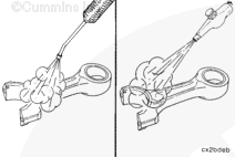
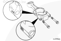
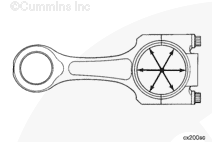
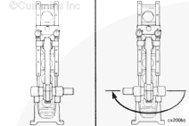
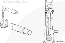
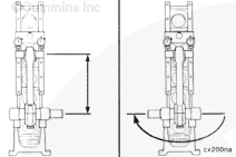
Use checking fixture, Part Number ST-561, and mandrel set, Part Number 3376690, to inspect the bend and twist of the connecting rod.

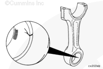
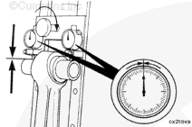
Calibrate the checking fixture with a new rod that has be measured for the correct center to center length, 217.975 to 218.025 mm [8.5817 to 8.5836 in].

Assemble the connecting rod cap to the rod. Refer to Procedure 001-054 in Section 1.

Assemble the connecting rod cap to the rod. Refer to Procedure 001-054 in Section 1.

SMALL | MEDIUM | LARGE


Install the piston pin mandrel, Part Number 3376693, from the mandrel set, Part Number 3376690, into the piston pin bore.

Install the mandrel, Part Number 3376691, in the piston crankshaft bore and expand the mandrel.

Make sure the pin on the mandrel is down and locked in position in the center of the connecting rod.

SMALL | MEDIUM | LARGE


Install the connecting rod into the fixture.

Move the dial holder to position the contact points of the indicators on the mandrel in the piston pin bore.

Tighten the bracket to hold the indicators in position.

Set the dial indicators to zero (0).

SMALL | MEDIUM | LARGE


Remove the connecting rod from the fixture.

Turn the rod 180 degrees horizontally and install the rod into the fixture again.

SMALL | MEDIUM | LARGE


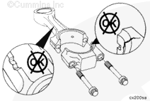
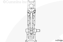
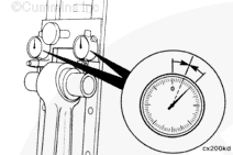
Check the dial indicators for zero (0) position again.

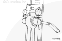
If the dial indicators show any change from zero (0), adjust the dials to half the indicated reading.

The fixture is now calibrated to allow the connecting rod to be installed into the fixture in either direction and the dials will indicate an equal defection on either side of the zero (0).

SMALL | MEDIUM | LARGE


Install the mandrel and arbor into the connecting rod to be inspected.

Install the connecting rod into the fixture.

SMALL | MEDIUM | LARGE


Measure the rod length and bend (alignment).

Connecting Rod Length

mm in
217.975 MIN 8.5817
218.025 MAX 8.5836

Connecting Rod Alignment (Bushing Installed)

mm in
0.10 MAX 0.004

SMALL | MEDIUM | LARGE


Install a feeler gauge between the mandrel and the dial indicator holding plate as shown.

Connecting Rod Twist (Bushing Installed)

mm in
0.25 MAX 0.010

Replace the connecting rod if not within specification.

SMALL | MEDIUM | LARGE
   

Finishing Steps

TOC

 WARNING 

Batteries can emit explosive gases. To reduce the possibility of personal injury, always ventilate the compartment before servicing the batteries. To reduce the possibility of arcing, remove the negative (-) battery cable first and attach the negative (-) battery cable last.

The piston and connecting rod must be installed as an assembly on M Series engines. Refer to Procedure 001-054 in Section 1.

SMALL | MEDIUM | LARGE
Last Modified:  21-Jan-2009