This component or assembly weighs greater than 23 kg [50 lb]. To prevent serious personal injury, be sure to have assistance or use appropriate lifting equipment to lift this component or assembly.
WARNING
Batteries can emit explosive gases. To reduce the possibility of personal injury, always ventilate the compartment before servicing the batteries. To reduce the possibility of arcing, remove the negative (-) battery cable first and attach the negative (-) battery cable last.
CAUTION
Place a wooden block, the width of the oil pan, between the floor jack and oil pan to prevent damage to the engine.
Remove the transmission, clutch, and all related components, if equipped. Refer to the OEM service manual.
This component or assembly weighs greater than 23 kg [50 lb]. To prevent serious personal injury, be sure to have assistance or use appropriate lifting equipment to lift this component or assembly.
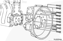
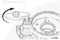
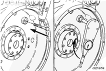
Remove the remaining capscrews.
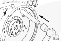
Use a rubber hammer to loosen the flywheel housing.
NOTE: Do not damage the rear of the oil pan gasket when removing the flywheel housing.
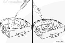
When using a steam cleaner, wear safety glasses or a face shield, as well as protective clothing. Hot steam can cause serious personal injury.
WARNING
When using solvents, acids, or alkaline materials for cleaning. follow the manufacturer’s recommendations for use. Wear goggles and protective clothing to reduce the possibility of personal injury.
WARNING
Wear appropriate eye and face protection when using compressed air. Flying debris and dirt can cause personal injury.
Use steam or solvent to clean the flywheel housing. Dry with compressed air.
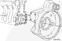
This component or assembly weighs greater than 23 kg [50 lb]. To prevent serious personal injury, be sure to have assistance or use appropriate lifting equipment to lift this component or assembly.
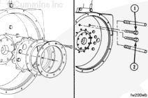
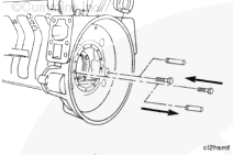
Use a hoist when installing the rear engine power take off flywheel housing over the guide pins.
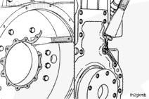
Do not damage the oil pan gasket when installing the flywheel housing.
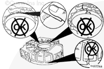
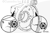
The flywheel housing bore must be aligned with the crankshaft. Do not tighten the capscrews to the final torque value until the flywheel housing is aligned.
Install the capscrews. Remove the guide pins, and install the remaining two capscrews.
Flywheel Housing Bore Alignment Maximum Total Indicator Reading
mm
SAE Number
in
0.30
00
0.012
0.25
0
0.010
0.25
1/2
0.010
0.20
1
0.008
0.20
2
0.008
0.20
3
0.008
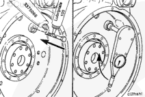
If the maximum bore alignment does not meet the specifications, use a rubber hammer to move the housing in the necessary direction, and repeat the measurement procedure.
If the bore alignment will not meet the specifications or the bore is not round, the housing must be replaced.
If bore and face alignment do not meet the specifications, loosen the housing capscrews. Tighten the capscrews, and measure the bore and face alignment again.
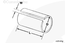
Manufacture a sleeve from 38.1-mm Outside Diameter [1.50-in] Outside Diameter (D) PVC, aluminum, thin wall hose, or equivalent, to the following dimensions:
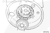
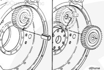
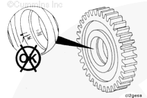
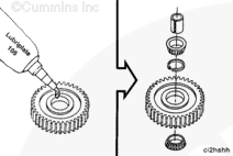
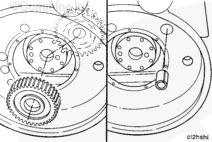
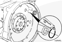
Apply Lubriplate™ 105, or equivalent, on the outer races and the bearings.
The outer bearing races of new replacement gears are already pressed into the gear.
Install the bearing and spacer into the idler gear. Use the manufactured sleeve to hold the bearing assembly together when installing the idler gear assembly.
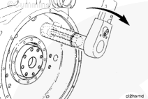
Apply Lubriplate™ 105 under the head of the idler shaft capscrew. Insert the capscrew through the idler shaft. Tighten the installation capscrew with a torque wrench.
The torque needed to draw the idler shaft in place must not exceed 88 N•m [65 ft-lb]. If installation torque exceeds this amount, it indicates misalignment between the bore and the shaft. Remove the idler shaft and install it again.
After the idler shaft has been seated, remove the capscrew.
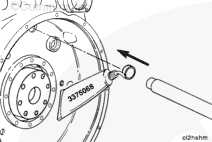
Apply pipe sealant, Part Number 3375066, to the threads of the idler shaft capscrew. Apply Lubriplate™ 105 under the head of the capscrew. Install the capscrew and tighten to its final torque value.
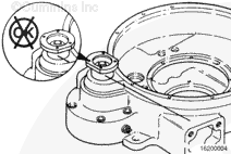
Turn the output flange so that the flat sides are on the top and bottom. This prevents any interference when the transmission is installed onto the housing.
This component or assembly weighs greater than 23 kg [50 lb]. To prevent serious personal injury, be sure to have assistance or use appropriate lifting equipment to lift this component or assembly.
WARNING
Batteries can emit explosive gases. To reduce the possibility of personal injury, always ventilate the compartment before servicing the batteries. To reduce the possibility of arcing, remove the negative (-) battery cable first and attach the negative (-) battery cable last.
CAUTION
Place a wooden block, the width of the oil pan, between the floor jack and oil pan to prevent damage to the engine.
Hello, I'm Jack, a diesel engine fan and a blogger. I write about how to fix and improve diesel engines, from cars to trucks to generators. I also review the newest models and innovations in the diesel market. If you are interested in learning more about diesel engines, check out my blog and leave your feedback.
View all posts by Jack
 WARNING
  CAUTION


;)
;)
;)
;)
;)
;)
;)
;)
;)
;)
;)
;)
;)
;)
;)
;)
;)
;)
;)
;)
;)
;)
;)
;)
;)
;)
;)
;)
;)
;)
;)
;)
;)
;)
;)
;)
;)
;)
;)
;)
;)
;)
;)
;)
;)
;)
;)
;)
;)
;)
;)
;)
;)
;)
;)
;)
;)
;)
;)
;)
;)
;)
;)
;)
;)
;)