|
Mixer Inlet Pressure Sensor Circuit – Shorted High
|

Overview
Mixer Inlet Pressure Sensor Circuit – Shorted High
| CODE | REASON | EFFECT |
| Fault Code: 122 PID: P102 SPN: 102 FMI: 3 LAMP: Amber SRT: |
Mixer Inlet Pressure Sensor Circuit – Voltage above normal, or shorted to high source. High signal voltage detected on the mixer inlet pressure signal pin at the ECM. |
Engine power derate. |
|
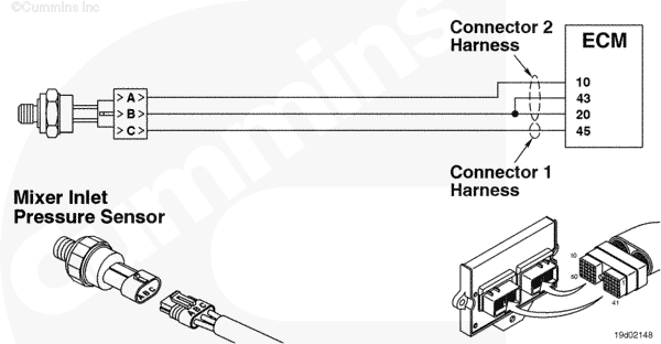
Mixer Inlet Pressure Sensor Circuit |
 |
Circuit Description
The Mixer Inlet Pressure Sensor measures the inlet air pressure entering the fuel housing.
Component Location
The Mixer Inlet Pressure Sensor is located in the air inlet elbow.
Shop Talk
If the Mixer Inlet Pressure Sensor is disconnected, the engine can continue operating by using the accelerator plate position and the manifold pressure to estimate the mixer inlet pressure. Before performing any wiring checks, disconnect the sensor from the engine harness.
Cautions and Warnings
 CAUTION CAUTION To reduce the possibility of damaging a new ECM, all other active fault codes must be investigated prior to replacing the ECM. |
|
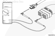
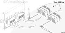
CAUTION To reduce the possibility of pin and harness damage, use the following test leads when taking a measurement: |
Troubleshooting Steps
| STEPS | SPECIFICATIONS | |
|---|---|---|
| STEP 1. | Check the fault codes. | |
| STEP 1A. Read the fault codes. | Fault Code 227 active? | |
| STEP 1B. Check for an inactive fault code. | Fault Code 122 inactive? | |
| STEP 2. | Check the Mixer Inlet Pressure Sensor and circuit. | |
| STEP 2A. Inspect the Mixer Inlet Pressure Sensor connector pins. | Dirty or damaged pins? | |
| STEP 2B. Check for circuit response. | Fault Code 123 active and Fault Code 122 inactive? | |
| STEP 2C. Check the sensor supply voltage and return circuit. | 4.5 VDC to 5.25 VDC? | |
| STEP 2D. Check the fault codes and verify sensor condition. | Fault Code 122 active? | |
| STEP 3. | Check the ECM and engine harness. | |
| STEP 3A. Inspect the ECM and engine harness connector pins. | Dirty or damaged pins? | |
| STEP 3B. Check for an open circuit in the engine harness. | Less than 10 ohms? | |
| STEP 3C. Check for a pin to pin short circuit in the engine harness. | More than 100k ohms? | |
| STEP 3D. Check for a pin to pin short circuit in the engine harness. | More than 100k ohms? | |
| STEP 3E. Check for an inactive fault code. | Fault Code 122 inactive? | |
| STEP 4. | Clear the fault codes. | |
| STEP 4A. Disable the fault code. | Fault Code 122 inactive? | |
| STEP 4B. Clear the inactive fault codes. | All fault codes cleared? | |
Guided Step 1 – Check the fault codes.
| Guided Step 1A – Read the fault codes. | |
|---|---|
Conditions
ActionUse INSITE™ electronic service tool to read the fault codes. |
|
|
Fault Code 227 active? |
|
| YES | NO |
| No Repair | No Repair |
|
Fault Code 227.
|
|
| Guided Step 1B – Check for inactive fault codes. | |
|---|---|
Conditions
Action
|
|
|
Fault Code 122 inactive? |
|
| YES | NO |
| No Repair | No Repair |
|
Inactive or Intermittent Fault Code, Procedure 019-362
|
|
Guided Step 2 – Check the Mixer Inlet Pressure Sensor and circuit.
| Guided Step 2A – Inspect the Mixer Inlet Pressure Sensor and connector pins. | |
|---|---|
Conditions
Action
For general inspection techniques, refer to Component Connector and Pin Inspection, Procedure 019-361. |
|
|
Dirty or damaged pins? |
|
| YES | NO |
|
Repair the damaged pins. Flush the dirt, debris, or moisture from the connector pins. Repair or replace the engine harness, or replace the sensor, whichever has the damaged pins.
|
No Repair |
| Guided Step 2B – Check the circuit response. | |
|---|---|
Conditions
Action
|
|
|
Fault Code 123 active and Fault Code 122 inactive? |
|
| YES | NO |
| No Repair | No Repair |
| Guided Step 2C – Check the sensor supply voltage and return circuit. | ||
|---|---|---|
Conditions
Action
Refer to the wiring diagram for connector pin identification. |
|
|
|
4.5 VDC to 5.25 VDC? |
||
| YES | NO | |
| No Repair | No Repair | |
| Guided Step 2D – Check the fault codes and verify sensor condition. | |
|---|---|
Conditions
Action
|
|
|
Fault Code 122 active? |
|
| YES | NO |
|
Replace the Mixer Inlet Pressure Sensor. Refer to Procedure 019-098 |
No Repair |
Guided Step 3 – Check the ECM and engine harness.
| Guided Step 3A – Inspect the ECM and engine harness connector pins. | |
|---|---|
Conditions
Action
For general inspection techniques, refer to Component Connector and Pin Inspection, Procedure 019-361. |
|
|
Dirty or damaged pins? |
|
| YES | NO |
|
Repair the damaged pins. Flush the dirt, debris, or moisture from the connector pins. Repair or replace the engine harness, or replace the ECM, whichever has the damaged pins.
|
No Repair |
| Guided Step 3B – Check for an open circuit in the engine harness. | ||
|---|---|---|
Conditions
Action
Refer to the wiring diagram for connector pin identification. For general resistance measurements refer to Resistance Measurements Using a Multimeter and Wiring Diagram, Procedure 019-360. |
|
|
|
Less than 10 ohms? |
||
| YES | NO | |
| No Repair |
Repair or replace the engine harness. |
|
| Guided Step 3C – Check for a pin to pin short circuit in the engine harness. | ||
|---|---|---|
Conditions
Action
Refer to the wiring diagram for connector pin identification. For general resistance measurements refer to Resistance Measurements Using a Multimeter and Wiring Diagram, Procedure 019-360. |
|
|
|
More than 100K ohms? |
||
| YES | NO | |
| No Repair |
Repair or replace the engine harness. |
|
;)
;)
;)
;)
;)
;)
;)
;)
| Guided Step 3D – Check for a pin to pin short circuit in the engine harness. | |
|---|---|
Conditions
Action
Refer to the wiring diagram for connector pin identification. For general resistance measurements refer to Resistance Measurements Using a Multimeter and Wiring Diagram, Procedure 019-360. |
|
|
More than 100k ohms? |
|
| YES | NO |
| No Repair |
Repair or replace the engine harness. |
| Guided Step 3E – Check for an inactive fault code. | |
|---|---|
Conditions
Action
|
|
|
Fault Code 122 active? |
|
| YES | NO |
| No Repair |
|
Guided Step 4 – Clear the fault codes.
| Guided Step 4A – Disable the fault code. | |
|---|---|
Conditions
Action
|
|
|
Fault Code 122 inactive? |
|
| YES | NO |
| No Repair | No Repair |
| Guided Step 4B – Clear the inactive fault codes. | |
|---|---|
Conditions
Action
|
|
|
All fault codes cleared? |
|
| YES | NO |
| No Repair | No Repair |
|
Repair complete
|
Appropriate troubleshooting charts
|