|
Engine Oil Pressure Sensor Circuit – Shorted High
|

Overview
| CODE | REASON | EFFECT |
| Fault Code: 135 PID: P100 SPN: 100 FMI: 3 LAMP: Amber SRT: |
Oil Pressure Sensor Circuit – Voltage Above Normal, or Shorted to High Source. High signal voltage detected on the engine oil pressure sensor pin at the ECM. |
None on performance. No engine protection for oil pressure. |
|
Engine Oil Pressure Sensor Circuit |
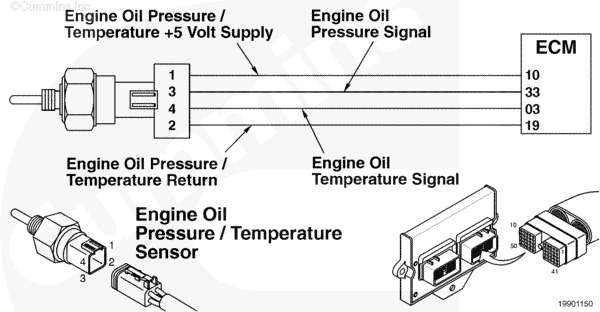 |
Circuit Description
The engine oil pressure/temperature sensor is used by the electronic control module (ECM) to monitor the lubricating oil pressure. The ECM monitors the voltage on the signal pin and converts this to a pressure value. The oil pressure value is used by the ECM for the engine protection system.
Component Location
The oil pressure/temperature sensor is located in the block, beneath the ECM.
Shop Talk
- Does the fault occur only in cold weather? If so, allow the oil to warm up and see if the fault goes inactive.
- Engine operating in altitudes above 5000 feet with auxiliary oil filtering devices can experience low oil pressure faults at idle conditions.
Cautions and Warnings
 CAUTION CAUTION To reduce the possibility of damaging a new ECM, all other active fault codes must be investigated prior to replacing the ECM. |
|
CAUTION To reduce the possibility of pin and harness damage, use the appropriate breakout cable when taking a measurement. |
|
CAUTION To reduce the possibility of pin and harness damage, use the following test leads when taking a measurement: |
Troubleshooting Steps
| STEPS | SPECIFICATIONS | |
|---|---|---|
| STEP 1. | Check the fault codes. | |
| STEP 1A. Check for 386 fault codes. | Fault Code 386 active? | |
| STEP 1B. Check for an inactive fault code. | Fault Code 135 inactive? | |
| STEP 2. | Check the oil pressure sensor and circuit. | |
| STEP 2A. Inspect the oil pressure sensor and connector pins. | Dirty or damaged pins? | |
| STEP 2B. Check the circuit response. | Fault Code 141 active and Fault Code 135 inactive? | |
| STEP 2C. Check the sensor supply voltage and return circuit. | 4.5 to 5.25 VDC? | |
| STEP 2D. Check for fault codes and verify sensor condition. | Fault Code 135 active? | |
| STEP 3. | Check the ECM and engine harness. | |
| STEP 3A. Inspect the ECM and engine harness connector pins. | Dirty or damaged pins? | |
| STEP 3B. Check for an open circuit in the engine harness. | Less than 10 ohms? | |
| STEP 3C. Check for a pin to pin short circuit in the engine harness. | Greater than 100k ohms? | |
| STEP 3D. Check for a pin to pin short circuit in the engine harness. | Greater than 100k ohms? | |
| STEP 3E. Check for an inactive fault code. | Fault Code 135 inactive? | |
| STEP 4. | Clear the fault codes. | |
| STEP 4A. Disable the fault code. | Fault Code 135 inactive? | |
| STEP 4B. Clear the inactive fault codes. | All fault codes cleared? | |
Guided Step 1 – Check the fault codes.
| Guided Step 1A – Check for 386 fault codes. | |
|---|---|
Conditions
Action
|
|
|
Fault Code 386 active? |
|
| YES | NO |
| No Repair | No Repair |
|
Fault Code 386
|
|
| Guided Step 1B – Check for an inactive fault code. | |
|---|---|
Conditions
Action
|
|
|
Fault Code 135 inactive? |
|
| YES | NO |
| No Repair | No Repair |
Guided Step 2 – Check the oil pressure sensor and circuit.
| Guided Step 2A – Inspect the oil pressure sensor and connector pins. | |
|---|---|
Conditions
Action
For general inspection techniques, refer to Component Connector and Pin Inspection, Procedure 019-361. |
|
|
Dirty or damaged pins? |
|
| YES | NO |
|
A defective connection has been detected in the sensor or harness connector. Repair the damaged pins. Repair or replace the engine harness, or replace the sensor, whichever has the damaged pins.
|
No Repair |
| Guided Step 2B – Check the circuit response. | |
|---|---|
Conditions
Action
|
|
|
Fault Code 141 active and Fault Code 135 inactive? |
|
| YES | NO |
| No Repair | No Repair |
| Guided Step 2C – Check the sensor supply voltage and return circuit. | |
|---|---|
Conditions
Action
|
|
|
4.5 to 5.25 VDC? |
|
| YES | NO |
| No Repair | No Repair |
| Guided Step 2D – Check the fault codes and verify sensor condition. | |
|---|---|
Conditions
Action
|
|
|
Fault Code 135 active? |
|
| YES | NO |
|
A defective sensor has been detected. Replace the oil pressure sensor. Refer to Procedure 019-155 or 019-066. |
No Repair |
Guided Step 3 – Check the ECM and engine harness.
| Guided Step 3A – Inspect the ECM and engine harness connector pins. | |
|---|---|
Conditions
Action
For general inspection techniques, refer to Component Connector and Pin Inspection, Procedure 019-361. |
|
|
Dirty or damaged pins? |
|
| YES | NO |
|
A defective connection has been detected in the ECM connector 1 or engine harness connector. Repair the damaged pins. Repair or replace the engine harness, whichever has the damaged pins. |
No Repair |
| Guided Step 3B – Check for an open circuit in the engine harness. | |
|---|---|
Conditions
Action
Refer to the circuit diagram or wiring diagram for connector pin identification. For general resistance measurement techniques, refer to the Resistance Measurements Using a Multimeter and Wiring Diagram, Procedure 019-360. |
|
|
Less than 10 ohms? |
|
| YES | NO |
| No Repair |
An open circuit has been detected in the engine harness. Repair the damaged pins. Repair or replace the engine harness, whichever has the damaged pins. |
| Guided Step 3C – Check for a pin to pin short circuit in the engine harness. | ||
|---|---|---|
Conditions
Action
Refer to the circuit diagram or wiring diagram for connector pin identification. For general resistance measurement techniques, refer to the Resistance Measurements Using a Multimeter and Wiring Diagram, Procedure 019-360. |
|
|
|
Greater than 100k ohms? |
||
| YES | NO | |
| No Repair |
A pin to pin short circuit on the SIGNAL line has been detected in the engine harness. Repair the damaged pins. Repair or replace the engine harness, whichever has the damaged pins. |
|
;)
;)
;)
;)
| Guided Step 3D – Check for a pin to pin short circuit in the engine harness. | |
|---|---|
Conditions
Action
Refer to the circuit diagram or wiring diagram for connector pin identification. For general resistance measurement techniques, refer to the Resistance Measurements Using a Multimeter and Wiring Diagram, Procedure 019-360. |
|
|
Greater than 100k ohms? |
|
| YES | NO |
| No Repair |
A pin to pin short circuit on the SUPPLY line has been detected in the engine harness. Repair the damaged pins. Repair or replace the engine harness, whichever has the damaged pins. |
| Guided Step 3E – Check for an inactive fault code. | |
|---|---|
Conditions
Action
|
|
|
Fault Code 135 inactive? |
|
| YES | NO |
| No Repair |
Replace the ECM. Call for pre-authorization. Refer to Procedure 019-031. |
Guided Step 4 – Clear the fault codes.
| Guided Step 4A – Disable the fault code. | |
|---|---|
Conditions
Action
|
|
|
Fault Code 135 inactive? |
|
| YES | NO |
| No Repair | No Repair |
| Guided Step 4B – Clear the inactive fault codes. | |
|---|---|
Conditions
Action
|
|
|
All fault codes cleared? |
|
| YES | NO |
| No Repair | No Repair |
|
Repair complete
|
Appropriate troubleshooting charts
|