Overview
Fault Code: 198
PID: S122
SPN: 612
FMI: 4
LAMP: Yellow
SRT:
|
ECM Diagnostic Lamp Circuit – Shorted Low. Open circuit detected on diagnostic lamp pins in the engine harness ECM connector 2.
|
No effect on performance. Loss of diagnostic lamp.
|
|
ECM Diagnostic Lamp Circuit |
|
|
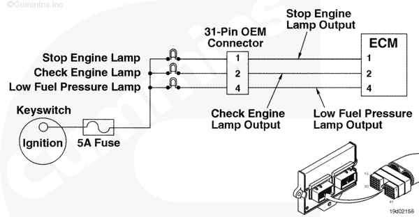
Circuit Description
These are the three malfunction-indicator lamps for the electronic control module (ECM).
Component Location
The three malfunction-indicator lamps are installed on the dashboard by the OEM.
Shop Talk
Each of the three malfunction-indicator lamps will be a different color. The stop engine lamp is red. The check engine lamp is yellow. The low fuel pressure lamp is green. For exact circuitry information, refer to the OEM troubleshooting and repair manual.
Cautions and Warnings
 CAUTION
To reduce the possibility of damaging a new ECM, all other active fault codes must be investigated prior to replacing the ECM.
|
CAUTION
To reduce the possibility of pin and harness damage, use the following test lead when taking a measurement:
Part Number 3822758 – male Deutsch/AMP/Metri-Pack test lead.
|
Troubleshooting Steps
| STEPS |
SPECIFICATIONS |
| STEP 1. |
Check the fault codes. |
|
| |
STEP 1A. Read the fault codes. |
Fault Code 198 active? |
| STEP 2. |
Check the ECM diagnostic lamp circuit. |
|
| |
STEP 2A. Inspect the OEM and engine harness connector pins. |
Dirty or damaged pins? |
| |
STEP 2B. Read the fault codes. |
Fault Code 198 active? |
| |
STEP 2C. Check for a short circuit to ground. |
More than 100k ohms? |
| STEP 3. |
Check the engine harness. |
|
| |
STEP 3A. Inspect the engine harness and ECM connector pins. |
Dirty or damaged pins? |
| |
STEP 3B. Read the fault codes. |
Fault Code 198 active? |
| |
STEP 3C. Check for a short circuit to ground. |
More than 100k ohms? |
| |
STEP 3D. Check for a short circuit from pin to pin. |
More than 100k ohms? |
| STEP 4. |
Clear the fault codes. |
|
| |
STEP 4A. Disable the fault code. |
Fault Code 198 inactive? |
| |
STEP 4B. Clear the inactive fault codes. |
All fault codes cleared? |
Guided Step 1 – Check the fault codes.
| Guided Step 1A – Read the fault codes. |
Conditions
- Turn keyswitch ON
- Connect the INSITE™ electronic service tool.
Action
- Use INSITE™ electronic service tool to read the fault codes.
|
|
Fault Code 198 active?
|
| YES |
NO |
| No Repair |
No Repair |
|
|
|
Guided Step 2 – Check the ECM diagnostic lamp circuit.
| Guided Step 2A – Inspect the OEM and engine harness connector pins. |
Conditions
- Turn keyswitch OFF
- Disconnect the OEM harness from the engine harness at the 31-pin OEM connector.
Action
- Corroded pins
- Bent or broken pins
- Pushed back or expanded pins
- Moisture in or on the connector
- Missing or damaged connector seals
- Dirt or debris in or on the connector pins.
|
|
Dirty or damaged pins?
|
| YES |
NO |
|
Repair the damaged pins. Repair or replace the OEM harness or engine harness, whichever has the damaged pins.
- Flush the dirt, debris, or moisture from the connector pins using electronic contact cleaner, Part Number 3824510.
- Install the appropriate connector seal if it is damaged or missing.
- Repair the OEM harness. Refer to the OEM troubleshooting and repair manual.
- Replace the OEM harness. Refer to the OEM troubleshooting and repair manual.
- Repair the engine harness. Refer to Procedure 019-208
- Replace the engine harness. Refer to Procedure 019-043.
|
No Repair |
|
|
|
| Guided Step 2B – Read the fault codes. |
Conditions
- Connect all components
- Turn keyswitch ON
- Connect INSITE™ electronic service tool.
Action
- Start the engine and let it idle for one minute.
- Use INSITE™ electronic service tool to read the fault codes.
|
|
Fault Code 198 active?
|
| YES |
NO |
| No Repair |
No Repair |
|
|
|
| Guided Step 2C – Check for a short circuit to ground. |
Conditions
- Turn keyswitch OFF
- Disconnect the OEM harness from the engine harness at the 31-pin OEM connector
- Disconnect the stop engine lamp, check engine lamp, maintenance lamp, and low fuel pressure lamp from the OEM harness.
Action
- Measure the resistance from the stop engine lamp output pin in the 31-pin OEM connector, OEM side, to engine block ground.
- Measure the resistance from the check engine lamp output pin in the 31-pin OEM connector, OEM side, to engine block ground.
- Measure the resistance from the low fuel pressure lamp output pin in the 31-pin OEM connector, OEM side, to engine block ground.
|
|
|
More than 100k ohms?
|
| YES |
NO |
| No Repair |
Repair or replace the OEM harness.
- Repair the OEM harness. Refer to the OEM troubleshooting and repair manual.
- Replace the OEM harness. Refer to the OEM troubleshooting and repair manual.
|
|
|
|
Guided Step 3 – Check the engine harness.
| Guided Step 3A – Inspect the engine harness and ECM connector pins. |
Conditions
- Turn keyswitch OFF.
- Disconnect engine harness connector 1 and connector 2 from the ECM.
Action
- Corroded pins
- Bent or broken pins
- Pushed back or expanded pins
- Moisture in or on the connector
- Missing or damaged connector seals
- Dirt or debris in or on the connector pins.
|
|
Dirty or damaged pins?
|
| YES |
NO |
|
Repair the damaged pins. Repair or replace the engine harness, or replace the ECM, whichever has the damaged pins.
- Flush the dirt, debris, or moisture from the connector pins using electronic contact cleaner, Part Number 3824510.
- Install the appropriate connector seal if it is damaged or missing.
- Repair the engine harness. Refer to Procedure 019-204.
- Replace the engine harness. Refer to Procedure 019-043.
- Replace the ECM. Call for pre-authorization. Refer to Procedure 019-031.
|
No Repair |
|
|
|
| Guided Step 3B – Read the fault codes. |
Conditions
- Connect all components
- Turn keyswitch ON
- Connect INSITE™ electronic service tool.
Action
- Start the engine and let it idle for one minute.
- Use INSITE™ electronic service tool to read the fault codes.
|
|
Fault Code 198 active?
|
| YES |
NO |
| No Repair |
No Repair |
|
|
|
| Guided Step 3C – Check for a short circuit to ground. |
Conditions
- Turn keyswitch OFF
- Disconnect the OEM harness from the engine harness at the 31-pin OEM connector
- Disconnect engine harness connector 2 from the ECM.
Action
- Measure the resistance from the stop engine lamp output pin in engine harness ECM connector 2 to engine block ground.
- Measure the resistance from the check engine lamp output pin in engine harness ECM connector 2 to engine block ground.
- Measure the resistance from the low fuel pressure lamp output pin in engine harness ECM connector 2 to engine block ground.
|
|
|
More than 100k ohms?
|
| YES |
NO |
| No Repair |
Repair or replace the engine harness.
- Repair the engine harness. Refer to Procedure 019-204.
- Replace the engine harness. Refer to Procedure 019-043.
|
|
|
|
| Guided Step 3D – Check for a short circuit from pin to pin. |
Conditions
- Turn keyswitch OFF
- Disconnect the OEM harness from the engine harness at the 23-pin and 31-pin OEM connectors
- Disconnect engine harness connector 1 and connector 2 from the ECM.
Action
- Measure the resistance from the stop engine lamp output pin in harness ECM connector 2 to all other pins in the connector, and to all pins in engine harness ECM connector 1.
- Measure the resistance from the check engine lamp output pin in harness ECM connector 2 to all other pins in the connector, and to all pins in engine harness ECM connector 1.
- Measure the resistance from the low fuel pressure lamp output pin in harness ECM connector 2 to all other pins in the connector, and to all pins in engine harness ECM connector 1.
|
|
|
More than 100k ohms?
|
| YES |
NO |
| No Repair |
Repair or replace the engine harness.
- Repair the engine harness. Refer to Procedure 019-204.
- Replace the engine harness. Refer to Procedure 019-043.
|
|
|
|
Guided Step 4 – Clear the fault codes.
| Guided Step 4A – Disable the fault code. |
Conditions
- Connect all components
- Turn keyswitch ON
- Connect INSITE™ electronic service tool.
Action
- Start the engine and let it idle for one minute.
- Use INSITE™ electronic service tool verify that Fault Code 198 is inactive.
|
|
Fault Code 198 inactive?
|
| YES |
NO |
| No Repair |
Troubleshooting procedures need to be repeated from the beginning.
|
|
|
|
| Guided Step 4B – Clear the inactive fault codes. |
Conditions
- Connect all components
- Turn keyswitch ON
- Connect INSITE™ electronic service tool.
Action
- Use INSITE™ electronic service tool to erase the inactive fault codes.
|
|
All fault codes cleared?
|
| YES |
NO |
| No Repair |
Troubleshoot any remaining active fault codes.
|
|
Repair complete
|
Appropriate troubleshooting charts
|
Last Modified: 06-Aug-2004

;)
;)
;)
;)
;)
;)
;)
;)