|
Compressor Inlet Pressure Sensor Circuit – Shorted Low
|

Overview
Compressor Inlet Pressure Sensor Circuit – Shorted Low
| CODE | REASON | EFFECT |
| Fault Code: 222 PID: P108 SPN: 108 FMI: 4 LAMP: Amber SRT: |
Compressor Inlet Pressure Sensor Circuit – Voltage Below Normal, or Shorted to Low Source. Low signal voltage detected on the compressor inlet pressure circuit at the ECM. |
None |
|
Compressor Inlet Pressure Sensor Circuit |
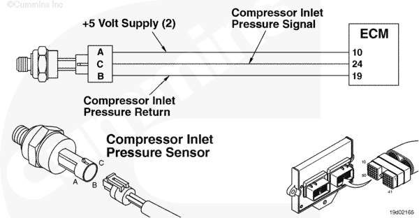 |
Circuit Description
The compressor inlet pressure sensor measures the inlet pressure to the turbocharger.
Component Location
The compressor inlet pressure sensor is located just prior to the inlet to the turbocharger.
Shop Talk
This sensor is also considered an inlet restriction sensor and measures pressure in absolute pressure.
Troubleshooting Steps
| STEPS | SPECIFICATIONS | |
|---|---|---|
| STEP 1. | Check the fault codes. | |
| STEP 1A. Check for fault codes. | Fault Code 352 active? | |
| STEP 1B. Check for an inactive fault code. | Fault Code 222 inactive? | |
| STEP 2. | Check the compressor inlet pressure sensor and circuit. | |
| STEP 2A. Inspect the compressor inlet pressure sensor and connector pins. | Dirty or damaged pins? | |
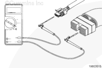
| STEP 2B. Check the sensor supply voltage and return circuit. | 4.5 to 5.25 VDC? | |
| STEP 2C. Check the circuit response. | Fault Code 221 active and Fault Code 222 inactive? | |
| STEP 2D. Check the fault codes and verify sensor condition. | Fault Code 222 active? | |
| STEP 3. | Check the ECM and engine harness. | |
| STEP 3A. Inspect the ECM and engine harness connector pins. | Dirty or damaged pins? | |
| STEP 3B. Check for an open circuit in the engine harness. | Less than 10 ohms? | |
| STEP 3C. Check for an open circuit in the engine harness. | Less than 10 ohms? | |
| STEP 3D. Check for a pin to pin short circuit in the engine harness. | Greater than 100k ohms? | |
| STEP 3E. Check for a pin short circuit to ground. | Greater than 100k ohms? | |
| STEP 3F. Check for an inactive fault code. | Fault Code 222 inactive? | |
| STEP 4. | Clear the fault code. | |
| STEP 4A. Disable the fault code. | Fault Code 222 inactive? | |
| STEP 4B. Clear the inactive fault codes. | All fault codes cleared? | |
Guided Step 1 – Check the fault codes.
| Guided Step 1A – Check for fault codes. | |
|---|---|
Conditions
Action
|
|
|
Fault Code 352 active? |
|
| YES | NO |
| No Repair | No Repair |
|
Fault Code 352
|
|
| Guided Step 1B – Check for an inactive fault code. | |
|---|---|
Conditions
Action
|
|
|
Fault Code 222 inactive? |
|
| YES | NO |
| No Repair | No Repair |
Guided Step 2 – Check the compressor inlet pressure sensor and circuit.
| Guided Step 2A – Inspect the compressor inlet pressure sensor and connector pins. | |
|---|---|
Conditions
Action
Refer to the circuit diagram or wiring diagram for component pin identification. For general inspection techniques, refer to Component Connector and Pin Inspection, Procedure 019-361. |
|
|
Dirty or damaged pins? |
|
| YES | NO |
|
A defective connection has been detected in the sensor or harness connection. Repair the damaged pins. Repair or replace the engine harness, or replace the sensor, whichever has the damaged pins.
|
No Repair |
| Guided Step 2B – Check the sensor supply voltage and return circuit. | |
|---|---|
Conditions
Action
Refer to the circuit diagram or wiring diagram for connector pin identification. |
|
|
4.5 to 5.25 VDC? |
|
| YES | NO |
| No Repair | No Repair |
| Guided Step 2C – Check the circuit response. | |
|---|---|
Conditions
ActionCheck for the appropriate circuit response after 30 seconds.
|
|
|
Fault Code 221 active and Fault Code 222 inactive? |
|
| YES | NO |
| No Repair | No Repair |
| Guided Step 2D – Check the fault codes and verify sensor condition. | |
|---|---|
Conditions
Action
|
|
|
Fault Code 222 active? |
|
| YES | NO |
|
A defective sensor has been detected, Replace the compressor inlet pressure sensor. Refer to Procedure 019-433. |
No Repair |
Guided Step 3 – Check the ECM and engine harness.
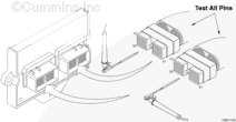
| Guided Step 3A – Inspect the ECM and engine harness connector pins. | |
|---|---|
Conditions
Action
Refer to the circuit diagram or wiring diagram for component pin identification. For general inspection techniques, refer to Component Connector and Pin Inspection, Procedure 019-361. |
|
|
Dirty or damaged pins? |
|
| YES | NO |
|
A defective connection has been detected in the ECM connector or engine harness connector. Repair the damaged pins. Repair or replace the engine harness, whichever has the damaged pins. |
No Repair |
| Guided Step 3B – Check for an open circuit in the engine harness. | |
|---|---|
Conditions
Action
Refer to the circuit diagram or wiring diagram for component pin identification. For general inspection techniques, refer to Component Connector and Pin Inspection, Procedure 019-360. |
|
|
Less than 10 ohms? |
|
| YES | NO |
| No Repair |
An open SUPPLY circuit has been detected in the engine harness Repair or replace the engine harness, whichever has the damaged pins. |
| Guided Step 3C – Check for an open circuit in the engine harness. | ||
|---|---|---|
Conditions
Action
Refer to the circuit diagram or wiring diagram for component pin identification. For general inspection techniques, refer to Component Connector and Pin Inspection, Procedure 019-360. |
|
|
|
Less than 10 ohms? |
||
| YES | NO | |
| No Repair |
An open SUPPLY circuit has been detected in the engine harness Repair or replace the engine harness, whichever has the damaged pins. |
|
| Guided Step 3D – Check for a pin to pin short circuit in the engine harness. | ||
|---|---|---|
Conditions
Action
Refer to the circuit diagram or wiring diagram for component pin identification. For general inspection techniques, refer to Component Connector and Pin Inspection, Procedure 019-360. |
|
|
|
Greater than 100k ohms? |
||
| YES | NO | |
| No Repair |
An pin to pin short circuit on the SIGNAL line has been detected in the engine harness Repair or replace the engine harness, whichever has the damaged pins. |
|
;)
;)
;)
;)
;)
;)
| Guided Step 3E – Check for a pin short circuit to ground. | |
|---|---|
Conditions
Action
Refer to the circuit diagram or wiring diagram for component pin identification. For general inspection techniques, refer to Component Connector and Pin Inspection, Procedure 019-360. |
|
|
Greater than 100k ohms? |
|
| YES | NO |
| No Repair |
An pin to ground short circuit on the SIGNAL line has been detected in the engine harness Repair or replace the engine harness, whichever has the damaged pins. |
| Guided Step 3F – Check for an inactive fault code. | |
|---|---|
Conditions
Action
|
|
|
Fault Code 222 inactive? |
|
| YES | NO |
| No Repair |
Replace the ECM. Call for pre-authorization. Refer to Procedure 019-031. |
Guided Step 4 – Clear the fault code.
| Guided Step 4A – Disable the fault code. | |
|---|---|
Conditions
Action
|
|
|
Fault Code 222 inactive? |
|
| YES | NO |
| No Repair | No Repair |
| Guided Step 4B – Clear the inactive fault codes. | |
|---|---|
Conditions
Action
|
|
|
All fault codes cleared? |
|
| YES | NO |
| No Repair | No Repair |
|
Repair complete
|
Appropriate troubleshooting steps
|