|
Exhaust Back Pressure Low Warning – Under Pressure
|

Overview
| CODE | REASON | EFFECT |
| Fault Code: 2319 PID: S34 SPN: 648 FMI: 1/18 LAMP: Amber SRT: |
Exhaust Back Pressure Low – Warning. Low exhaust back pressure or the sensor signal line has been broken. |
Possible reduced performance. |
|
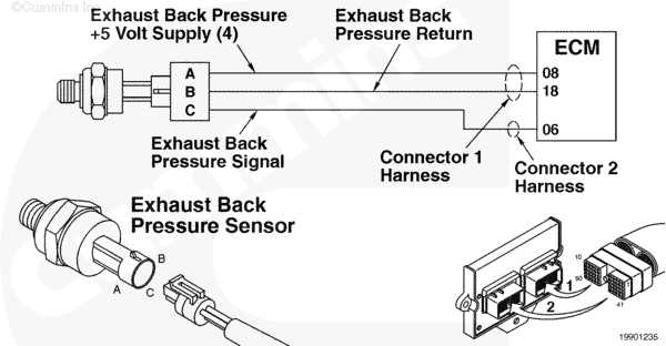
Exhaust Back Pressure Sensor Circuit |
 |
;)
;)
Circuit Description
The electronic control module (ECM) uses this sensor’s input to determine the pressure of the exhaust gas, which affects the fueling of the engine.
Component Location
The exhaust back pressure sensor is located above the rocker housing and attached to the closed-crankcase ventilation filter bracket.
Shop Talk
The arrangement of this sensor allows some condensation/sludge buildup within the tube arrangement. Before replacing the sensor, make sure this tube is free from blockage.
On the L Gas Plus, an OEM tube from the exhaust connects to a boiler box on the exhaust side of the engine. A tube then connects the box to the exhaust back pressure sensor.
A broken or disconnected exhaust back pressure tube will cause this fault to be active.
Troubleshooting Steps
| STEPS | SPECIFICATIONS | |
|---|---|---|
| STEP 1. | Check the exhaust back pressure. | |
| STEP 1A. Check the exhaust back pressure with a mechanical gauge. | Pressure between 61 to 127 mm Hg [2.4 to 5.0 in Hg]? | |
| STEP 2. | Verify the sensor accuracy. | |
| STEP 2A. Compare the INSITE™ electronic service tool exhaust back pressure measurement with the mechanical gauge measurement. | Is INSITE™ electronic service tool measurement the same as pressure measured with gauge? | |
| STEP 2B. Inspect the exhaust back pressure sensor and engine harness connector pins. | Dirty or damaged pins? | |
| STEP 3. | Check the exhaust back pressure tube. | |
| STEP 3A. Inspect the exhaust back pressure tube for blockage. | Any blockage in tube? | |
| STEP 4. | Clear the fault codes. | |
| STEP 4A. Disable the fault code. | Fault Code 2319 inactive? | |
| STEP 4B. Clear the inactive fault codes. | All fault codes cleared? | |
Guided Step 1 – Check the exhaust back pressure.
| Guided Step 1A – Check the exhaust back pressure with a mechanical gauge. | |
|---|---|
Conditions
ActionNote: This test must be performed under stall test conditions. |
|
|
Pressure between 61 to 127 mm Hg [2.4 to 5.0 in Hg]? |
|
| YES | NO |
| No Repair |
Exhaust back pressure not to specification. Contact the OEM regarding the exhaust system (pipe, muffler, catalytic converter). |
Guided Step 2 – Verify the sensor accuracy.
| Guided Step 2A – Compare the INSITE™ electronic service tool exhaust back pressure measurement with the mechanical gauge measurement. | |
|---|---|
Conditions
Action
|
|
|
Is INSITE™ electronic service tool measurement the same as pressure measured with gauge? |
|
| YES | NO |
| No Repair | No Repair |
| Guided Step 2B – Inspect the exhaust back pressure sensor and engine harness connector pins. | |
|---|---|
Conditions
Action
|
|
|
Dirty or damaged pins? |
|
| YES | NO |
|
Repair or replace the engine harness, or replace the sensor, whichever has the damaged pins.
|
No Repair |
Guided Step 3 – Check the exhaust back pressure tube.
| Guided Step 3A – Inspect the exhaust back pressure tube for blockage. | |
|---|---|
Conditions
|
|
|
Any blockages in tube? |
|
| YES | NO |
|
Tube obstructed. Clean or replace the tube. |
Replace the sensor. Refer to Procedure 019-347. |
Guided Step 4 – Clear the fault codes.
| Guided Step 4A – Disable the fault code. | |
|---|---|
Conditions
Action
|
|
|
Fault Code 2319 inactive? |
|
| YES | NO |
| No Repair |
Troubleshooting procedures need to be repeated from the beginning. |
| Guided Step 4B – Clear the inactive fault codes. | |
|---|---|
Conditions
Action
|
|
|
All fault codes cleared? |
|
| YES | NO |
| No Repair |
Troubleshoot any remaining active fault codes. |
|
Repair complete
|
Appropriate troubleshooting charts
|