|
Engine Coolant Pressure Sensor Circuit – Shorted Low
|

Overview
| CODE | REASON | EFFECT |
| Fault Code: 232 PID: P109 SPN: 109 FMI: 4 LAMP: Amber SRT: |
Engine Coolant Pressure Sensor Circuit – Shorted Low |
None on performance. No engine protection for coolant pressure. |
|
Engine Coolant Pressure Sensor Circuit |
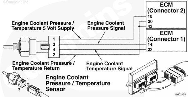 |
Circuit Description
The engine coolant pressure/temperature sensor is used by the electronic control module (ECM) to monitor the coolant pressure. The ECM monitors the voltage on the signal pin and converts this to a pressure value. The coolant pressure value is used by the ECM for the engine protection system.
Component Location
The coolant pressure/temperature sensor is located in the block, below the water outlet location.
Troubleshooting Steps
| STEPS | SPECIFICATIONS | |
|---|---|---|
| STEP 1. | Check the fault codes. | |
| STEP 1A. Check for fault codes. | Fault Code 352 active? | |
| STEP 1B. Check for an inactive fault code. | Fault Code 232 inactive? | |
| STEP 2. | Check the coolant pressure sensor and circuit. | |
| STEP 2A. Inspect the coolant pressure sensor and connector pins. | Dirty or damaged pins? | |
| STEP 2B. Check the sensor supply voltage and return circuit. | 4.5 to 5.25 VDC? | |
| STEP 2C. Check the circuit response. | Fault Code 232 active and Fault Code 231 inactive? | |
| STEP 2D. Check the fault codes and verify sensor condition. | Fault Code 231 active? | |
| STEP 3. | Check the ECM and engine harness. | |
| STEP 3A. Inspect ECM and engine harness connector pins. | Dirty or damaged pins? | |
| STEP 3B. Check for an open circuit in the engine harness. | Less than 10 ohms? | |
| STEP 3C. Check for an open circuit in the engine harness. | Less than 10 ohms? | |
| STEP 3D. Check for a pin to pin short circuit in the engine harness. | Greater than 100k ohms? | |
| STEP 3E. Check for a pin short circuit to ground. | Greater than 100k ohms? | |
| STEP 3F. Check for an inactive fault code. | Fault Code 231 inactive? | |
| STEP 4. | Clear the fault code. | |
| STEP 4A. Disable the fault code. | Fault Code 232 inactive? | |
| STEP 4B. Clear the inactive fault codes. | All fault codes cleared? | |
Guided Step 1 – Check the fault codes.
| Guided Step 1A – Check for fault codes. | |
|---|---|
Conditions
Action
|
|
|
Fault Code 352 active? |
|
| YES | NO |
| No Repair | No Repair |
|
Fault Code 352
|
|
| Guided Step 1B – Check for an inactive fault code. | |
|---|---|
Conditions
Action
|
|
|
Fault Code 232 inactive? |
|
| YES | NO |
| No Repair | No Repair |
Guided Step 2 – Check the coolant pressure sensor and circuit.
| Guided Step 2A – Inspect the coolant pressure sensor and connector pins. | |
|---|---|
Conditions
Action
For general inspection techniques, refer to Component Connector Pin Inspection, Procedure 019-361. |
|
|
Dirty or damaged pins? |
|
| YES | NO |
|
A defective connection has been detected in the sensor or harness connection. Repair the damaged pins. Repair or replace the engine harness, or replace the sensor, whichever has the damaged pins.
|
No Repair |
| Guided Step 2B – Check the sensor supply voltage and return circuit. | |
|---|---|
Conditions
Action
Refer to the circuit diagram or wiring diagram for connector pin identification. |
|
|
4.5 to 5.25 VDC? |
|
| YES | NO |
| No Repair | No Repair |
| Guided Step 2C – Check the circuit response. | |
|---|---|
Conditions
ActionCheck for the appropriate circuit response after 30 seconds.
|
|
|
Fault Code 231 active and Fault Code 232 inactive? |
|
| YES | NO |
| No Repair | No Repair |
| Guided Step 2D – Check the fault codes and verify sensor condition. | |
|---|---|
Conditions
Action
|
|
|
Fault Code 232 active? |
|
| YES | NO |
|
A defective sensor has been detected, Replace the coolant pressure sensor. Refer to Procedure 019-157. |
No Repair |
Guided Step 3 – Check the ECM and engine harness.
| Guided Step 3A – Inspect the ECM and engine harness connector pins. | |
|---|---|
Conditions
Action
Refer to the circuit diagram or wiring diagram for component pin identification. For general inspection techniques, refer to Component Connector and Pin Inspection, Procedure 019-361. |
|
|
Dirty or damaged pins? |
|
| YES | NO |
|
A defective connection has been detected in the ECM connector or engine harness connector. Repair the damaged pins. Repair or replace the engine harness, whichever has the damaged pins. |
No Repair |
| Guided Step 3B – Check for an open circuit in the engine harness. | |
|---|---|
Conditions
Action
Refer to the circuit diagram or wiring diagram for component pin identification. For general inspection techniques, refer to Component Connector and Pin Inspection, Procedure 019-360. |
|
|
Less than 10 ohms? |
|
| YES | NO |
| No Repair |
An open supply circuit has been detected in the engine harness Repair or replace the engine harness, whichever has the damaged pins. |
| Guided Step 3C – Check for an open circuit in the engine harness. | |
|---|---|
Conditions
Action
Refer to the circuit diagram or wiring diagram for component pin identification. For general inspection techniques, refer to Component Connector and Pin Inspection, Procedure 019-360. |
|
|
Less than 10 ohms? |
|
| YES | NO |
| No Repair |
An open signal circuit has been detected in the engine harness Repair or replace the engine harness, whichever has the damaged pins. |
| Guided Step 3D – Check for a pin to pin short circuit in the engine harness. | ||
|---|---|---|
Conditions
Action
Refer to the circuit diagram or wiring diagram for component pin identification. For general inspection techniques, refer to Component Connector and Pin Inspection, Procedure 019-360. |
|
|
|
Greater than 100k ohms? |
||
| YES | NO | |
| No Repair |
An pin to pin short circuit on the signal line has been detected in the engine harness Repair or replace the engine harness, whichever has the damaged pins. |
|
;)
;)
;)
;)
| Guided Step 3D – Check for a pin short circuit to ground. | |
|---|---|
Conditions
Action
Refer to the circuit diagram or wiring diagram for component pin identification. For general inspection techniques, refer to Component Connector and Pin Inspection, Procedure 019-360. |
|
|
Greater than 100k ohms? |
|
| YES | NO |
| No Repair |
An pin to ground short circuit on the signal line has been detected in the engine harness Repair or replace the engine harness, whichever has the damaged pins. |
| Guided Step 3E – Check for an inactive fault code. | |
|---|---|
Conditions
Action
|
|
|
Fault Code 232 inactive? |
|
| YES | NO |
|
None. The removal and installation of the connector corrected the failure. |
Replace the ECM. Call for pre-authorization. Refer to Procedure 019-031. |
Guided Step 4 – Clear the fault code.
| Guided Step 4A – Disable the fault code. | |
|---|---|
Conditions
Action
|
|
|
Fault Code 232 inactive? |
|
| YES | NO |
| No Repair | No Repair |
| Guided Step 4B – Clear the inactive fault codes. | |
|---|---|
Conditions
Action
|
|
|
All fault codes cleared? |
|
| YES | NO |
| No Repair | No Repair |
|
Repair complete
|
Appropriate troubleshooting steps
|