|
Ignition Control Module Reference Signal Circuit – Shorted Low
|

Overview
| CODE | REASON | EFFECT |
| Fault Code: 462 PID: S66 SPN: 725 FMI: 4 LAMP: Red SRT: |
Ignition Control Module Reference Signal Circuit – Shorted Low. Low voltage detected at the ECM |
Engine will die or |
|
Ignition Reference Signal Circuit |
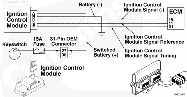 |
Circuit Description
The ignition control module (ICM) is a distributorless ignition module that provides a signal to the coils and delivers high voltage to the spark plugs. The electronic control module (ECM) controls the ICM by providing ignition timing information. The ICM for the C8.3G Plus engine is multispark, disengage-capable during idle conditions to smooth out idle operation
Component Location
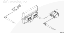
The ICM is located next to the ECM on the side of the engine
Shop Talk
The ICM can
not detect whether there is a misfire or a bad spark plug. For the ICM to operate correctly, all connectors
must be clean and tight. Cylinders 3 and 4 are especially critical to the proper operation of the ICM. A poor connection in either of these areas will cause the engine
not to start
Cautions and Warnings
 WARNING WARNING EXTREMELY HIGH VOLTAGE. Do not touch any ignition wiring or component while the engine is operating unless an insulated tool is being used to prevent electrical shock and damage to the equipment
|
 CAUTION CAUTION To reduce the possibility of damaging a new ECM, all other active fault codes must be investigated prior to replacing the ECM |
|
CAUTION To reduce the possibility of pin and harness damage, use the following test leads when taking a measurement: |
Troubleshooting Steps
| STEPS | SPECIFICATIONS | |
|---|---|---|
| STEP 1. | Check the fault codes. | |
| STEP 1A. Read the fault codes. | Fault Code 462 active? | |
| STEP 2. | Check the ignition control module. | |
| STEP 2A. Check the system voltage. | Less than 12-VDC? | |
| STEP 2B. Check the ICM supply voltage. | Less than 12-VDC? | |
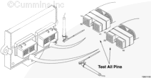
| STEP 2C. Inspect the ICM and engine harness connector pins. | Dirty or damaged pins? | |
| STEP 2D. Check the ICM supply voltage. | Less than 12-VDC? | |
| STEP 2E. Check for a damaged ICM 15 ampere fuse. | Less than 10 ohms? | |
| STEP 2F. Read the fault codes. | Fault Code 462 active? | |
| STEP 3. | Check the engine harness. | |
| STEP 3A. Inspect the engine harness and the ECM connector pins. | Dirty or damaged pins? | |
| STEP 3B. Check for an open circuit. | Less than 10 ohms? | |
| STEP 3C. Check for a short circuit to ground. | More than 100k ohms? | |
| STEP 3D. Check for a short circuit from pin to pin. | More than 100k ohms? | |
| STEP 3E. Check the ECM for active fault codes. | Fault Code 462 inactive? | |
| STEP 4. | Clear the fault codes. | |
| STEP 4A. Disable the fault code. | Fault Code 462 inactive? | |
| STEP 5B. Clear the inactive fault codes. | All fault codes cleared? | |
Guided Step 1 – Check the fault codes.
| Guided Step 1A – Read the fault codes. | |
|---|---|
Conditions
ActionRead the fault codes.
|
|
|
Fault Code 462 active? |
|
| YES | NO |
| No Repair | No Repair |
|
Use the following procedure for troubleshooting an inactive or intermittent fault code.
019-362 in Section 19. |
|
Guided Step 2 – Check the ignition control module (ICM).
| Guided Step 2A – Check the system voltage. | |
|---|---|
Conditions
ActionCheck the system voltage.
|
|
|
Less than 12-VDC? |
|
| YES | NO |
|
Recharge or replace the vehicle battery. |
No Repair |
| Guided Step 2B – Check the ICM supply voltage. | |
|---|---|
Conditions
ActionCheck the Switched Battery (+) voltage.
Refer to the circuit diagram or wiring diagram for component pin identification |
|
|
Less than 12-VDC? |
|
| YES | NO |
| No Repair | No Repair |
| Guided Step 2C – Inspect the ICM and engine harness connector pins. | |
|---|---|
Conditions
ActionInspect the module, engine harness, and OEM connector pins for the following:
Use the following procedure for general inspection techniques. |
|
|
Dirty or damaged pins? |
|
| YES | NO |
|
Repair the damaged pins. Repair or replace the engine harness, or replace the ICM, whichever has the damaged pins
|
No Repair |
| Guided Step 2D – Check the ICM supply voltage. | |
|---|---|
Conditions
ActionCheck the Switched Battery (+) voltage.
Refer to the circuit diagram or wiring diagram for component pin identification |
|
|
Less than 12-VDC? |
|
| YES | NO |
| No Repair | No Repair |
| Guided Step 2E – Check for a damaged ICM 15 ampere fuse. | |
|---|---|
Conditions
ActionCheck for a damaged fuse.
Refer to the circuit diagram or wiring diagram for component pin identification Use the following procedure for general resistance measurement techniques. |
|
|
Less than 10 ohms? |
|
| YES | NO |
| No Repair |
A damaged fuse has been detected. Replace the fuse |
| Guided Step 2F – Read the fault codes. | |
|---|---|
Conditions
ActionRead the fault codes.
|
|
|
Fault Code 462 active? |
|
| YES | NO |
| No Repair | No Repair |
Guided Step 3 – Check the engine harness.
| Guided Step 3A – Inspect the engine harness and the ECM connector pins. | |
|---|---|
Conditions
ActionInspect the engine harness, OEM 23-pin, OEM 31-pin, and ECM connector pins for the following:
Use the following procedure for general inspection techniques. |
|
|
Dirty or damaged pins? |
|
| YES | NO |
|
Repair the damaged pins. Repair or replace the engine harness, or replace the ECM, whichever has the damaged pins
|
No Repair |
| Guided Step 3B – Check for an open circuit. | ||
|---|---|---|
Conditions
ActionCheck for an open circuit.
Refer to the circuit diagram or wiring diagram for component pin identification Use the following procedure for general resistance measurement techniques. |
|
|
|
Less than 10 ohms? |
||
| YES | NO | |
| No Repair |
Repair or replace the engine harness
|
|
| Guided Step 3C – Check for a short circuit to ground. | ||
|---|---|---|
Conditions
ActionCheck for a short circuit to ground.
Refer to the circuit diagram or wiring diagram for component pin identification Use the following procedure for general resistance measurement techniques. |
|
|
|
More than 100k ohms? |
||
| YES | NO | |
| No Repair |
Repair or replace the engine harness
|
|
| Guided Step 3D – Check for a short circuit from pin to pin. | ||
|---|---|---|
Conditions
ActionCheck for a short circuit from pin to pin.
Refer to the circuit diagram or wiring diagram for component pin identification Use the following procedure for general resistance measurement techniques. |
|
|
|
Greater than 100k ohms? |
||
| YES | NO | |
| No Repair |
Repair or replace the engine harness
|
|
;)
;)
;)
;)
;)
;)
;)
;)
| Guided Step 3E – Check the ECM for active fault codes. | |
|---|---|
Conditions
ActionRead the fault codes.
|
|
|
Fault Code 462 inactive? |
|
| YES | NO |
| No Repair |
Replace the ICM. |
Guided Step 4 – Clear the fault codes.
| Guided Step 4A – Disable the fault code. | |
|---|---|
Conditions
ActionDisable the fault code.
|
|
|
Fault Code 462 inactive? |
|
| YES | NO |
| No Repair |
Return to the troubleshooting steps or contact a Cummins® Authorized Repair Location if all steps have been completed and checked again |
| Guided Step 4B – Clear the inactive fault codes. | |
|---|---|
Conditions
ActionClear the inactive fault codes.
|
|
|
All fault codes cleared? |
|
| YES | NO |
| No Repair |
Troubleshoot any remaining active fault codes |
|
Repair complete
|
Appropriate troubleshooting charts
|