|
Throttle Plate Position Sensor Circuit – Shorted High
|

Overview
| CODE | REASON | EFFECT |
| Fault Code: 512 PID: P51 SPN: 51 FMI: 3 LAMP: Amber SRT: |
Throttle Plate Position Sensor Circuit – Shorted High. High voltage detected at the Electronic Control Module (ECM). |
Possible reduced performance. |
|
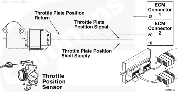
Throttle Plate Position Sensor Circuit |
 |
Circuit Description
The throttle plate position sensor is used by the electronic control module (ECM) to measure the percentage of throttle plate opening.
Component Location
The throttle plate position sensor is installed on top of the throttle body.
Shop Talk
Check to make sure that throttle linkage moves smoothly and freely.
Cautions and Warnings
 CAUTION CAUTION To reduce the possibility of damaging a new ECM, all other active fault codes must be investigated prior to replacing the ECM. |
|
CAUTION To reduce the possibility of pin and harness damage, use the following test leads when taking a measurement: |
Troubleshooting Steps
| STEPS | SPECIFICATIONS | |
|---|---|---|
| STEP 1. | Check the fault codes. | |
| STEP 1A. Check for an inactive fault code. | Fault Code 512 inactive? | |
| STEP 2. | Check the throttle plate position sensor and circuit. | |
| STEP 2A. Inspect the throttle plate position sensor and connector pins. | Dirty or damaged pins? | |
| STEP 2B. Check resistance of throttle plate position sensor. | Resistance less than 4800 Ohms? | |
| STEP 2C. Check for an inactive fault code. | Fault Code 512 inactive? | |
| STEP 3. | Check the engine control module and engine harness. | |
| STEP 3A. Inspect the engine control module and engine harness connector pins. | Dirty or damaged pins? | |
| STEP 3B. Check for a pin-to-pin short circuit in the engine harness. | Greater than 100k ohms? | |
| STEP 3C. Check for an inactive fault code. | Fault Code 512 inactive? | |
| STEP 4. | Clear the fault codes. | |
| STEP 4A. Disable the fault code. | Fault Code 512 inactive? | |
| STEP 4B. Clear the inactive fault codes. | All fault codes cleared? | |
Guided Step 1 – Check the fault codes.
| Guided Step 1A – Check for an inactive fault code. | |
|---|---|
Conditions
ActionCheck for an inactive fault code.
|
|
|
Fault Code 512 inactive? |
|
| YES | NO |
|
Inactive or intermittent fault code, refer to Procedure 019-362. |
No Repair |
Guided Step 2 – Check the throttle plate position sensor and circuit.
| Guided Step 2A – Inspect the throttle plate position sensor and connector pins. | |
|---|---|
Conditions
ActionInspect the engine harness and throttle posiition sensor connector pins for the following:
For general inspection techniques, refer to Component Connector and Pin Inspection, Procedure 019-361. |
|
|
Dirty or damaged pins? |
|
| YES | NO |
|
A defective connection has been detected in the sensor or engine harness connector. Clean the connector and pins. |
No Repair |
| Guided Step 2B – Check resistance of throttle plate position sensor. | |
|---|---|
Conditions
ActionCheck the resistance of the throttle plate position sensor.
|
|
|
Resistance less than 4800 Ohms? |
|
| YES | NO |
| No Repair |
Replace the throttle plate position sensor. Refer to Procedure 019-085. |
| Guided Step 2C – Check for an inactive fault code. | |
|---|---|
Conditions
ActionCheck for the appropriate circuit response after 30 seconds.
|
|
|
Fault Code 512 inactive? |
|
| YES | NO |
|
None. The removal and reinstallation of the connector corrected the failure. |
No Repair |
Guided Step 3 – Check the engine control module and engine harness.
| Guided Step 3A – Inspect the engine control module and engine harness connector pins. | |
|---|---|
Conditions
ActionInspect the engine harness and engine control module connector 1 pins for the following:
For general inspection techniques, refer to Component Connector and Pin Inspection, Procedure 019-361. |
|
|
Dirty or damaged pins? |
|
| YES | NO |
|
A defective connection has been detected in the engine control module connector 1 or the engine harness connector. Clean the connector and pins. Repair the damaged harness, connector, or pins if possible. |
No Repair |
| Guided Step 3B – Check for a pin-to-pin short circuit in the engine harness. | |
|---|---|
Conditions
ActionCheck for a pin-to-pin short circuit.
Use to the circuit diagram or wiring diagram for connector pin identification. For general resistance measurement techniques, refer to Resistance Measurements Using a Multimeter and Wiring Diagram, Procedure 019-360 |
|
|
Greater than 100k ohms? |
|
| YES | NO |
| No Repair |
A pin-to-pin short circuit on the throttle position sensor command (+) line for position signal line has been detected in the engine harness. |
| Guided Step 3C – Check for an inactive fault code. | |
|---|---|
Conditions
ActionCheck for the appropriate circuit response after 30 seconds.
|
|
|
Fault Code 512 inactive? |
|
| YES | NO |
|
None. The removal and reinstallation of the connector corrected the failure. |
Replace the ECM. Call for pre-authorization. Refer to Procedure 019-031. |
Guided Step 4 – Clear the fault codes.
| Guided Step 4A – Disable the fault code. | |
|---|---|
Conditions
ActionDisable the fault code.
|
|
|
Fault Code 512 inactive? |
|
| YES | NO |
| No Repair |
Return to the troubleshooting steps or contact a local Cummins Authorized Repair location if all steps have been completed and rechecked. |
| Guided Step 4B – Clear the inactive fault codes. | |
|---|---|
Conditions
ActionClear the inactive fault codes.
|
|
|
All fault codes cleared? |
|
| YES | NO |
| No Repair |
Troubleshoot any remaining active fault codes. |
|
Repair complete
|
Appropriate troubleshooting steps
|

;)
;)