|
Heated Oxygen Sensor Error
|

Overview
| CODE | REASON | EFFECT |
| Fault Code: 752 PID: S065 SPN: 723 FMI: 2 LAMP: Amber SRT: |
Heated Oxygen Sensor Error. The sensed air fuel ratio does not match the desired air fuel ratio. |
Possible reduced performance. No closed-loop operation. |
|
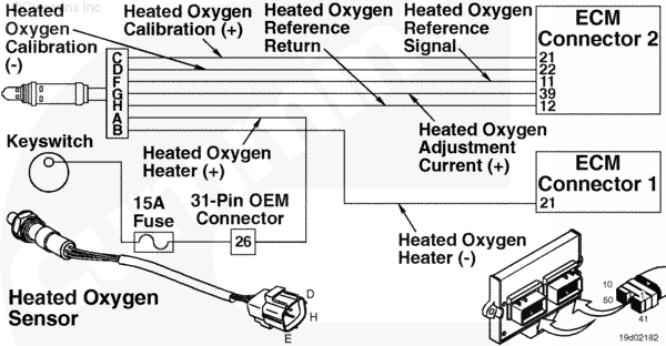
Heated Oxygen Sensor Circuit |
 |
;)
;)
Circuit Description
The electronic control module (ECM) uses this sensor to determine the composition of the exhaust gas and then, to adjust fueling.
Component Location
The heated oxygen sensor is located in the exhaust outlet connection, after the turbocharger.
Shop Talk
This fault is not typically caused by a failed heated oxygen sensor, but is a result of the engine running very lean or very rich. To determine if the engine is rich or lean, monitor the heated oxygen sensor compensation in INSITE™ electronic service tool.
Cautions and Warnings
 WARNING WARNING Do not touch the heated oxygen sensor until it has cooled. The heated oxygen sensor operates at high temperature and can cause personal injury.
|
 CAUTION CAUTION Do not use any lubricant in the heated oxygen sensor connector. The sensor will not perform correctly with any grease in the connector. |
|
CAUTION To reduce the possibility of damaging a new ECM, all other active fault codes must be investigated prior to replacing the ECM. |
Troubleshooting Steps
| STEPS | SPECIFICATIONS | |
|---|---|---|
| STEP 1. | Check the fault codes. | |
| STEP 1A. Check for multiple fault codes. | Fault Codes 453, 454, 455, 511, and/or 751 active? | |
| STEP 1B. Check for an inactive fault code. | Fault Code 752 inactive? | |
| STEP 2. | Check the fuel system. | |
| STEP 2A. Verify secondary fuel pressure. | Is pressure correct for the engine family? | |
| STEP 2B. Check for a stuck open or sticking fuel control valve. | Secondary fuel pressure drop within 50 seconds of key on? | |
| STEP 2C. Gas Mass Flow Compensation correct. | Is the gas flow compensation a positive 25 or higher? | |
| STEP 3. | Check Base engine components. | |
| STEP 3A. Check for an exhaust leak. | Any exhaust leaks? | |
| STEP 4. | Check the engine harness and heated oxygen sensor. | |
| STEP 4A. Check the engine harness and heated oxygen sensor connector pins. | Dirty or damaged pins? | |
| STEP 4B. Check for an open circuit in the heated oxygen sensor. | 2.9 to 3.7 ohms at room temperature? | |
| STEP 4C. Check the heated oxygen sensor heater supply voltage. | Voltage greater than 12 VDC? | |
| STEP 4C-1. Check for an open circuit in the engine harness. | ||
| STEP 4D. Check for an open circuit in the engine harness. | Less than 10 ohms? | |
| STEP 4E. Check for pin short to ground in the engine harness. | Less than 10 ohms? | |
| STEP 4F. Check for a pin to pin short circuit in the engine harness. | Greater than 100k ohms? | |
| STEP 4G. Verify oxygen sensor operation. | Did the sensor pass the test? | |
| STEP 5. | Clear the fault codes. | |
| STEP 5A. Disable the fault code. | Fault Code 752 inactive? | |
| STEP 5B. Clear the inactive fault codes. | All fault codes cleared? | |
Guided Step 1 – Check the fault codes.
| Guided Step 1A – Check for multiple fault codes. | |
|---|---|
Conditions
ActionCheck for multiple fault codes.
|
|
|
Fault Codes 453, 454, 455, 511, and/or 751 active? |
|
| YES | NO |
|
Troubleshoot any remaining fault codes before proceeding. |
No Repair |
|
Fault Codes 453, 454, 455, 511, or 751 first.
|
|
| Guided Step 1B – Check for an inactive fault code. | |
|---|---|
Conditions
ActionCheck for an inactive fault code.
|
|
|
Fault Code 752 inactive? |
|
| YES | NO |
| No Repair | No Repair |
|
Procedure 019-362
|
|
Guided Step 2 – Check the Fuel System.
| Guided Step 2A – Verify secondary fuel pressure. | |
|---|---|
Conditions
ActionMonitor the secondary fuel pressure.
B Gas Plus – 60 psia Minimum B LPG Plus – 40 psia Minimum C Gas Plus – 75 psia Minimum Note: All pressure sensors on the Gas Plus engines are absolute pressure sensors. Note: It might be necessary to perform a stall test to monitor dynamic secondary fuel pressure. If fuel pressure is not adequate, then the engine will surge under load, possibly causing this fault to occur. Refer to the Engine Performance Troubleshooting Tree in Section TT. |
|
|
Is pressure correct for the engine family? |
|
| YES | NO |
| No Repair |
Refer to the Engine Performance Troubleshooting Tree in Section TT. |
| Guided Step 2B – Check for a stuck open fuel control valve. | |
|---|---|
Conditions
ActionCheck for a stuck fuel control valve.
Note: If the fuel control valve is stuck open, raw fuel will be dumped into the engine and out the exhaust. This will cause the heated oxygen sensor to read a lower than actual air oxygen value. |
|
|
Secondary fuel pressure drop within 50 seconds of keyswitch on? |
|
| YES | NO |
|
A defective fuel control valve has been detected. Replace the fuel control valve. Refer to Procedure 019-102. Use INSITE™ electronic service tool to reset the fuel tables. |
No Repair |
| Guided Step 2C – Gas Mass Flow Compensation incorrect. | |
|---|---|
Conditions
ActionMonitor the gas mass flow compensation.
Note: Oil contamination of the gas mass flow sensor will cause a low flow reading and over-compensate for fuel flow. If the engine is running rich and a Fault Code 752 is active, the gas mass flow sensor must |
|
|
Is the gas flow compensation a positive 25 or higher? |
|
| YES | NO |
|
Replace the gas mass flow sensor. Refer to Procedure 019-101. Use INSITE™ electronic service tool to reset the fuel tables. |
No Repair |
Guided Step 3 – Check base engine components.
| Guided Step 3A – Check an exhaust leak. | |
|---|---|
Conditions
ActionCheck for an exhaust leak between the exhaust manifold and the heated oxygen sensor.
|
|
|
Any exhaust leaks? |
|
| YES | NO |
|
An exhaust leak has been detected. Repair or replace any exhaust component. Refer to Procedure 011-007 in the B5.9G, B5.9 LPG, B Gas Plus and B LPG Plus Troubleshooting and Repair Manual, Bulletin 3666164 and 011-007 in the C8.3g, C Gas Plus and L Gas Plus Troubleshooting and Repair Manual, Bulletin 3666206. |
No Repair |
Guided Step 4 – Check the engine harness and heated oxygen sensor.
| Guided Step 4A – Inspect the engine harness and heated oxygen sensor connector pins. | |
|---|---|
Conditions
ActionInspect the engine harness connector 2 and heated oxygen sensor connector pins for the following:
For general inspection techniques, refer to Components Connector and Pin Inspection, Procedure 019-361. |
|
|
Dirty or damaged pins? |
|
| YES | NO |
|
Repair the damaged pins. Replace the engine harness, or replace the sensor, whichever has the damaged pins. |
No Repair |
| Guided Step 4B – Check for an open circuit in the heated oxygen sensor. | |
|---|---|
Conditions
ActionCheck heated oxygen sensor resistance.
Refer to the circuit diagram or wiring diagram for connector pin identification. For general resistance measurement techniques, refer to Resistance Measurements Using a Multimeter and Wiring Diagram, Procedure 019-360 |
|
|
2.9 to 3.7 ohms at room temperature? |
|
| YES | NO |
| No Repair |
Replace the heated oxygen sensor. Refer to Procedure 019-100. Use INSITE™ electronic service tool to reset the fuel tables. |
| Guided Step 4C – Check the heated oxygen sensor heater supply voltage. | |
|---|---|
Conditions
ActionCheck the voltage at the heated oxygen sensor connector at the engine harness.
Refer to the circuit diagram or wiring diagram for connector pin identification. |
|
|
Voltage greater than 12 VDC? |
|
| YES | NO |
| No Repair | No Repair |
| Guided Step 4C-1 – Check for an open circuit in the engine harness. | |
|---|---|
Conditions
ActionCheck for an open circuit.
Refer to the circuit diagram or wiring diagram for connector pin identification. For general resistance measurement techniques, refer to Resistance Measurements Using a Multimeter and Wiring Diagram, Procedure 019-360 |
|
|
Less than 10 ohms? |
|
| YES | NO |
|
Check for a blown, corroded or wet fuse in the heated oxygen heater supply line in the OEM harness. Check for an open circuit in the OEM switched battery supply to the heated oxygen sensor supply. Repair the damaged pins. Replace the engine harness or OEM harness, whichever has the damaged pins.
|
An open return circuit has been detected in the engine harness. Repair or replace the engine harness. |
| Guided Step 4D – Check for an open circuit in the engine harness. | |
|---|---|
Conditions
ActionCheck for an open circuit.
Refer to the circuit diagram or wiring diagram for connector pin identification. For general resistance measurement techniques, refer to Resistance Measurements Using a Multimeter and Wiring Diagram, Procedure 019-360 |
|
|
Less than 10 ohms? |
|
| YES | NO |
| No Repair |
An open adjustment current signal or reference return circuit has been detected in the engine harness. Repair the damaged pins. Replace the engine harness, whichever has the damaged pins. |
| Guided Step 4E – Check for a pin short to ground in the engine harness. | |
|---|---|
Conditions
ActionCheck for an open circuit.
Refer to the circuit diagram or wiring diagram for connector pin identification. For general resistance measurement techniques, refer to Resistance Measurements Using a Multimeter and Wiring Diagram, Procedure 019-360 |
|
|
Less than 10 ohms? |
|
| YES | NO |
| No Repair |
A pin short to ground in the adjustment current or signal circuit has been detected in the engine harness. Repair the damaged pins. Replace the engine harness, whichever has the damaged pins. |
| Guided Step 4F – Check for a pin to pin short circuit in the engine harness. | |
|---|---|
Conditions
ActionCheck for a pin to pin short.
Refer to the circuit diagram or wiring diagram for connector pin identification. For general resistance measurement techniques, refer to Resistance Measurements Using a Multimeter and Wiring Diagram, Procedure 019-360 |
|
|
Greater than 100k ohms? |
|
| YES | NO |
| No Repair |
A pin to pin short circuit on the signal line or adjustment current line has been detected in the engine harness. Repair the damaged pins. Replace the engine harness, whichever has the damaged pins. |
| Guided Step 4G – Verify oxygen sensor operation. | |
|---|---|
Conditions
ActionPerform the heated oxygen sensor test using the INSITE™ electronic service tool.
|
|
|
Did the sensor pass the test? |
|
| YES | NO |
| No Repair |
Replace the heated oxygen sensor. Refer to Procedure 019-100. Use INSITE™ electronic service tool to reset the fuel tables. |
Guided Step 5 – Clear the fault codes.
| Guided Step 5A – Disable the fault code. | |
|---|---|
Conditions
ActionDisable the fault code.
|
|
|
Fault Code 752 inactive? |
|
| YES | NO |
| No Repair |
Return to troubleshooting steps or contact a local Cummins® authorized repair location if all steps have been completed and checked again. |
| Guided Step 5B – Clear the inactive fault codes. | |
|---|---|
Conditions
ActionClear the inactive fault codes.
|
|
|
All fault codes cleared? |
|
| YES | NO |
| No Repair |
Troubleshoot any remaining active fault codes. |
|
Repair complete
|
Appropriate troubleshooting charts
|