|
Engine Position Sensor Synchronization Error
|

Overview
| CODE | REASON | EFFECT |
| Fault Code: 753 PID: 21 SPN: 636 FMI: 2 LAMP: Amber SRT: |
Engine Speed/Position – Camshaft Synchronization Error. Invalid engine speed signal detected on the engine position sensor signal pins in the ECM. |
Engine can possibly die or will |
|
Engine Position Sensor Circuit |
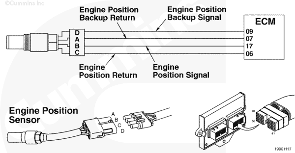 |
Circuit Description
The engine position sensor monitors the engine speed and position, then passes this information to the electronic control module (ECM) through the sensor harness.
Component Location
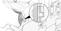
The engine position sensor is located in the gear housing, above the air compressor.
Shop Talk
The engine position sensor is a magnetic sensor and senses the raised material on the back of the camshaft gear to determine engine position and speed. There are seven raised material pieces on the back of the camshaft gear, one for each cylinder and one for timing.
Cautions and Warnings
 CAUTION CAUTION To reduce the possibility of pin and harness damage, use the following test lead when taking a measurement: |
Troubleshooting Steps
| STEPS | SPECIFICATIONS | |
|---|---|---|
| STEP 1. | Check the fault codes. | |
| STEP 1A. Read the fault codes. | Fault Code 753 active? | |
| STEP 2. | Check the engine position sensor. | |
| STEP 2A. Inspect the engine harness and engine position sensor connector pins. | Dirty or damaged pins? | |
| STEP 2B. Inspect the sensor for damage. | Damage found? | |
| STEP 2C. Check the resistance of the sensor. | 1000 to 2000 ohms? | |
| STEP 2D. Check for a short circuit to ground. | Greater than 100k ohms? | |
| STEP 2E. Read the fault codes. | Fault Code 753 active? | |
| STEP 2F. Verify adequate camshaft speed/position sensor air gap. | Distance is between 33.81 mm [1.33 in] and 34.06 mm [1.34 in]? | |
| STEP 3. | Clear the fault codes. | |
| STEP 3A. Disable the fault code. | Fault Code 753 inactive? | |
| STEP 3B. Clear the inactive fault codes. | All fault codes cleared? | |
Guided Step 1 – Check the fault codes.
| Guided Step 1A – Read the fault codes. | |
|---|---|
Conditions
ActionRead the fault codes. Use INSITE™ electronic service tool to read the fault codes. |
|
|
Fault Code 753 active? |
|
| YES | NO |
| No Repair | No Repair |
Guided Step 2 – Check the engine position sensor.
| Guided Step 2A – Inspect the engine harness and engine position sensor connector pins. | |
|---|---|
Conditions
ActionInspect the engine harness and engine position sensor connector pins for the following:
Use the following procedure for general inspection techniques. |
|
|
Dirty or damaged pins? |
|
| YES | NO |
|
Repair the damaged pins. Replace the engine harness, or replace the sensor, whichever has the damaged pins.
|
No Repair |
| Guided Step 2B – Inspect the sensor for damage. | |
|---|---|
Conditions
ActionInspect the engine position sensor for the following:
|
|
|
Damage found? |
|
| YES | NO |
|
Replace the sensor. Inspect the camshaft tone wheel/gear teeth for damage or spinning. For B Series engines, use the following procedure in the B5.9G, B5.9LPG, B Gas Plus, B LPG Gas Plus Engines Troubleshooting and Repair Manual, Bulletin 3666164. |
No Repair |
| Guided Step 2C – Check the resistance of the sensor. | ||
|---|---|---|
Conditions
ActionCheck the resistance of the sensor.
Refer to the circuit diagram or wiring diagram for connector pin identification. Use the following procedure for general resistance measurement techniques. |
|
|
|
1000 to 2000 ohms? |
||
| YES | NO | |
| No Repair |
Replace the sensor. |
|
| Guided Step 2D – Check for a short circuit to ground. | ||
|---|---|---|
Conditions
ActionCheck for a short circuit to ground.
Refer to the circuit diagram or wiring diagram for connector pin identification. Use the following procedure for general resistance measurement techniques. |
|
|
|
Greater than 100k ohms? |
||
| YES | NO | |
| No Repair |
Repair or replace the sensor.
|
|
| Guided Step 2E – Read the fault codes. | |
|---|---|
Conditions
ActionRead the fault codes.
|
|
|
Fault Code 753 active? |
|
| YES | NO |
| No Repair |
The removal and installation of the connector corrected the failure. |
| Guided Step 2F – Verify adequate camshaft speed/position sensor air gap. | ||
|---|---|---|
Conditions
ActionVerify adequate air gap.
|
|
|
|
Distance is between 33.81 mm [1.33 in] and 34.06 mm [1.34 in]? |
||
| YES | NO | |
| No Repair |
Inspect the camshaft tone wheel/gear teeth for damage or spinning. For B Series engines, use the following procedure in the B5.9G, B5.9LPG, B Gas Plus, B LPG Gas Plus Engines Troubleshooting and Repair Manual, Bulletin 3666164. |
|
;)
;)
;)
;)
;)
;)
;)
;)
Guided Step 3 – Clear the fault codes.
| Guided Step 3A – Disable the fault code. | |
|---|---|
Conditions
ActionDisable the fault code.
|
|
|
Fault Code 753 inactive? |
|
| YES | NO |
| No Repair |
Troubleshooting procedures need to be repeated from the beginning. |
| Guided Step 3B – Clear the inactive fault codes. | |
|---|---|
Conditions
ActionClear the inactive fault codes.
|
|
|
All fault codes cleared? |
|
| YES | NO |
| No Repair |
Troubleshoot any remaining active fault codes. |
|
Repair complete
|
Appropriate troubleshooting charts
|