|
Engine Speed/Position Camshaft Synchronization Error
|

Overview
| CODE | REASON | EFFECT |
| Fault Code: 753 PID: S064 SPN: 723 FMI: 2 LAMP: Amber SRT: |
Engine Speed/Position Camshaft Synchronization Error. Invalid engine speed signal detected on the engine position sensor signal pins in the ECM connector. |
Engine can die or will not start. |
|
Engine Position Sensor Circuit |
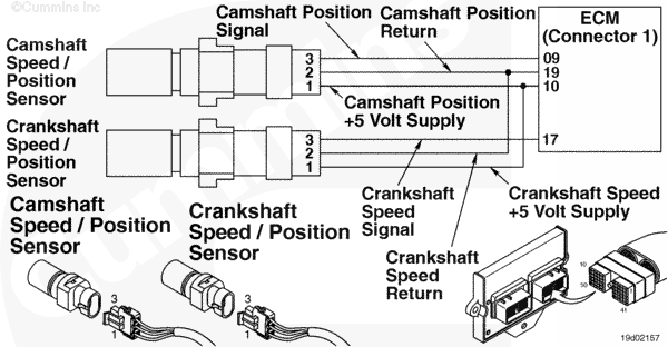 |
Circuit Description
The camshaft engine speed/position sensor provides engine speed information to the electronic control module (ECM). The sensor is powered by 5 volts. The sensor generates the signal by sensing the movement of target teeth machined into a tone wheel that is mounted to the camshaft.
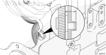
Component Location
The camshaft speed/position sensor is located on the intake side of the engine above the accessory drive. Refer to Procedure 100-002 for a detailed component location view.
Shop Talk
This fault code is recorded when the ECM does not receive a signal from the camshaft engine speed sensor, or the signal it receives is degrading.
Possible causes of this fault code include: open circuit on the supply, signal, or return circuits in the sensor, engine harness, or ECM.
Short circuits to ground or return circuits in the sensor, engine harness, or ECM.
Short circuits to a voltage source in the sensor, engine harness, or ECM.
Damage to the sensor target teeth or tone wheel.
If this fault code occurs intermittently, look closely for causes of intermittent harness connections such as loose or worn pins in the engine harness connectors.
Cautions and Warnings
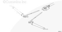
 CAUTION CAUTION To reduce the possibility of pin and harness damage, use the following test lead when taking a measurement: |
Troubleshooting Steps
| STEPS | SPECIFICATIONS | |
|---|---|---|
| STEP 1. | Check the fault codes. | |
| STEP 1A. Check for sensor supply fault codes. | Fault Code 352 or 386 active? | |
| STEP 1B. Check for an inactive fault code. | Fault Code 753 inactive? | |
| STEP 2. | Check the camshaft speed/position sensor and circuit. | |
| STEP 2A. Inspect the camshaft speed/position sensor and connector pins. | Dirty or damaged pins? | |
| STEP 2B. Check the sensor supply voltage and return circuit. | 4.75 to 5.25 VDC? | |
| STEP 2C. Inspect the camshaft speed/position sensor. | Damage sensor tip? | |
| STEP 2D. Verify adequate camshaft speed/position senor air gap. | Distance is between 30.16 mm [1.19 in] and 31.27 mm [1.23 in]? | |
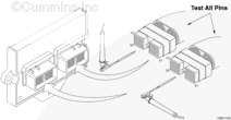
| STEP 3. | Check the ECM and engine harness. | |
| STEP 3A. Inspect the ECM and engine harness connector pins. | Dirty or damaged pins? | |
| STEP 3B. Check for an inactive fault code. | Fault Code 753 inactive? | |
| STEP 3C. Check for an open circuit in the engine harness. | Less than 10 ohms? | |
| STEP 3D. Check for a pin to pin short circuit in the engine harness. | Greater than 100k ohms? | |
| STEP 3E. Check for a pin to pin short circuit in the engine harness. | Greater than 100k ohms? | |
| STEP 3F. Check for a pin short circuit to ground. | Greater than 100k ohms? | |
| STEP 3G. Check for an inactive fault code. | Fault Code 753 inactive? | |
| STEP 4. | Clear the fault codes. | |
| STEP 4A. Disable the fault code. | Fault Code 753 inactive? | |
| STEP 4B. Clear the inactive fault codes. | All fault codes cleared? | |
Guided Step 1 – Check the fault codes.
| Guided Step 1A – Check for sensor supply fault codes. | |
|---|---|
Conditions
Action
|
|
|
Fault Code 352 or 386 active? |
|
| YES | NO |
| No Repair | No Repair |
|
Fault Code 352 or 386
|
|
| Guided Step 1B – Check for an inactive fault code. | |
|---|---|
Conditions
Action
|
|
|
Fault Code 753 inactive? |
|
| YES | NO |
| No Repair | No Repair |
|
Procedure 019-362
|
|
Guided Step 2 – Check the camshaft speed/position sensor and circuit.
| Guided Step 2A – Inspect the camshaft speed/position sensor and connector pins. | |
|---|---|
Conditions
Action
For general inspection techniques, refer to Components Connector and Pin Inspection, Procedure 019-361. |
|
|
Dirty or damaged pins? |
|
| YES | NO |
|
A defective connection has been detected in the sensor or harness connection. Repair the damaged pins. Replace the engine harness, whichever has the damaged pins. |
No Repair |
| Guided Step 2B – Check the sensor supply voltage and return circuit. | ||
|---|---|---|
Conditions
Action
Refer to the circuit diagram or wiring diagram for component pin identification. |
|
|
|
4.75 to 5.25 VDC? |
||
| YES | NO | |
| No Repair | No Repair | |
| Guided Step 2C – Inspect the camshaft speed/position sensor. | |
|---|---|
Conditions
Action
|
|
|
Damaged sensor tip? |
|
| YES | NO |
|
A defective sensor has been detected. Replace the camshaft speed/position sensor. Refer to Procedure 019-365. Inspect the camshaft tone wheel/gear teeth for damage or spinning. Sensor clearance is between 30.16 mm [1.19 in] and 31.27 mm [1.23 in]. Refer to Procedure 001-013 in the Troubleshooting and Repair Manual, C8.3G, C Gas Plus and L Gas Plus Engines, Bulletin 3666206. |
No Repair |
| Guided Step 2D – Verify adequate camshaft speed/position sensor air gap. | ||
|---|---|---|
Conditions
Action
|
|
|
|
Distance is between 30.16 mm [1.19 in] and 31.27 mm [1.23 in]? |
||
| YES | NO | |
| No Repair |
Inspect the camshaft tone wheel/gear teeth for damage or spinning. Refer to Procedure 001-013 in the Troubleshooting and Repair Manual, C8.3G, C Gas Plus and L Gas Plus Engines, Bulletin 3666206. |
|
Guided Step 3 – Check the ECM and engine harness.
| Guided Step 3A – Inspect the ECM and engine harness connector pins. | |
|---|---|
Conditions
Action
For general inspection techniques, refer to Components Connector and Pin Inspection, Procedure 019-361. |
|
|
Dirty or damaged pins? |
|
| YES | NO |
|
A defective connection has been detected in the ECM connector 1 or engine harness connector. Repair the damaged pins. Replace the engine harness.
|
No Repair |
| Guided Step 3B – Check for an inactive fault code. | |
|---|---|
Conditions
Action
|
|
|
Fault Code 753 inactive? |
|
| YES | NO |
| No Repair | No Repair |
| Guided Step 3C – Check for an open circuit in the engine harness. | |
|---|---|
Conditions
Action
Shake and wiggle the harness to determine an intermittent connection. Refer to the circuit diagram or wiring diagram for connector pin identification. For general resistance measurement techniques, refer to Resistance Measurements Using a Multimeter and Wiring Diagram, Procedure 019-360 |
|
|
Less than 10 ohms? |
|
| YES | NO |
| No Repair |
An open return current has been detected in the engine harness. Repair the damaged pins. Replace the engine harness, whichever has the damaged pins. |
| Guided Step 3D – Check for a pin to pin short circuit in the engine harness. | ||
|---|---|---|
Conditions
Action
Refer to the circuit diagram or wiring diagram for connector pin identification. For general resistance measurement techniques, refer to Resistance Measurements Using a Multimeter and Wiring Diagram, Procedure 019-360 |
|
|
|
Greater than 100k ohms? |
||
| YES | NO | |
| No Repair |
A pin to pin short circuit on the signal line has been detected in the engine harness. Repair the damaged pins. Replace the engine harness, whichever has the damaged pins. |
|
;)
;)
;)
;)
;)
;)
;)
;)
| Guided Step 3E – Check for a pin to pin short circuit in the engine harness. | ||
|---|---|---|
Conditions
Action
Refer to the circuit diagram or wiring diagram for connector pin identification. For general resistance measurement techniques, refer to Resistance Measurements Using a Multimeter and Wiring Diagram, Procedure 019-360 |
|
|
|
Greater than 100k ohms? |
||
| YES | NO | |
| No Repair |
A pin to pin short circuit on the supply line has been detected in the engine harness. Repair the damaged pins. Replace the engine harness, whichever has the damaged pins. |
|
| Guided Step 3F – Check for a pin short to ground. | |
|---|---|
Conditions
Action
Refer to the circuit diagram or wiring diagram for connector pin identification. For general resistance measurement techniques, refer to Resistance Measurements Using a Multimeter and Wiring Diagram, Procedure 019-360 |
|
|
Greater than 100k ohms? |
|
| YES | NO |
| No Repair |
A pin to ground short circuit on the signal line has been detected in the engine harness. Repair the damaged pins. Replace the engine harness, whichever has the damaged pins. |
| Guided Step 3G – Check for an inactive fault code. | |
|---|---|
Conditions
Action
|
|
|
Fault Code 753 inactive? |
|
| YES | NO |
| No Repair | No Repair |
Guided Step 4 – Clear the fault codes.
| Guided Step 4A – Disable the fault code. | |
|---|---|
Conditions
Action
|
|
|
Fault Code 753 inactive? |
|
| YES | NO |
| No Repair | No Repair |
| Guided Step 4B – Clear the inactive fault codes. | |
|---|---|
Conditions
Action
|
|
|
All fault codes cleared? |
|
| YES | NO |
| No Repair | No Repair |
|
Repair complete
|
Appropriate troubleshooting charts
|