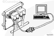
Disconnect the OEM harness connector from the ECM. Insert a test lead into the governor type switch signal pin and attach it to the multimeter probe.
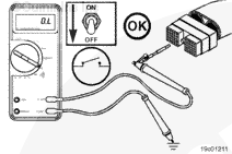
Touch the other probe to engine block ground. Transition the switch to the alternate position. Be sure the circuit shows a closed circuit (10 ohms or less). If the circuit is not closed in one of the positions then inspect the governor type switch signal wire for an open circuit.
If the resistance is within specification, the governor type switch signal wire must be checked for short circuit to ground, short circuit from pin to pin, and a short circuit to external voltage.
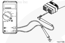
Connect one of the multimeter probes to the governor type switch signal wire. Touch the other probe to chassis ground. Move the switch to the alternate position and measure the resistance.
The multimeter must show an open circuit (100k ohms or more). If the circuit does not show an open circuit then there is a short to ground in the circuit somewhere. Repair or replace the OEM harness according to the OEM troubleshooting procedures.
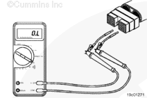
Check for a short circuit from pin to pin. Insert one test lead into the governor type switch signal pin and insert the other test lead into the switch return pin. Measure the resistance. The multimeter must show an open circuit (100k ohms or more).
Remove the test lead from the switch return pin and test all other pins in the connector. The multimeter must show an open circuit on all pins. Repair any pin circuits that show a closed circuit with the governor type switch signal pin.
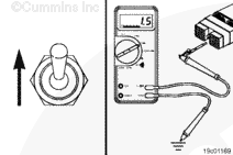
Close the governor type switch and set the multimeter to read VDC.
Insert one test lead into the governor type switch signal pin and connect a multimeter lead to it. Touch the other multimeter lead to engine block ground. Measure the voltage. The multimeter must show 1.5 VDC or less. If the voltage is not correct, there is an external voltage source connected to the circuit. Repair or replace the OEM wiring to correct the issue.
Hello, I'm Jack, a diesel engine fan and a blogger. I write about how to fix and improve diesel engines, from cars to trucks to generators. I also review the newest models and innovations in the diesel market. If you are interested in learning more about diesel engines, check out my blog and leave your feedback.
View all posts by Jack


;)
;)
;)
;)
;)
;)
;)
;)
;)
;)