Disconnect the air intake pipe from the turbocharger. Refer to the OEM service manual.
Remove the alternator, if necessary. Refer to Procedure 013-001 in the Troubleshooting and Repair Manual, Signature, ISX and QSX15 Engines, Bulletin 3666239.
Do not use connector grease on the EGR valve position sensor connector. Use of connector grease can cause damage to the EGR valve and low engine performance.
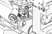
Disconnect the wiring harness connector from the Exhaust Gas Recirculation
(EGR) valve position sensor connector.
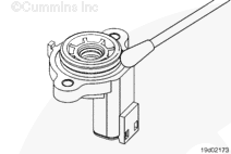
There are two types of position sensors. The original position sensor has the connector molded into the sensor (as shown). the new hull effect sensor has a pigtail harness connected to the sensor.
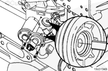
Make sure the EGR valve position sensor is properly aligned with the EGR sector shaft before installing. Misalignment upon installation can damage the sensor.
Inspect the position sensor for a damaged or missing o-ring and damaged or broken connector pins.
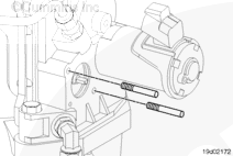
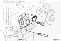
Guide pins, Part Number 3165138, are necessary for proper alignment between the position sensor and the housing. Improper alignment will result in damage to the sensor.
Insert alignment pins into the capscrew holes in the housing.
Do not apply any type of lubricant or grease on the position sensor connector or position sensor wiring harness connector. Lubricant or grease can cause inaccurate voltage signals due to insufficient connector engagement, which are then sent to the Electronic Control Module (ECM).
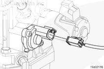
Connect the engine harness connector to the sensor. Push the connectors together until they lock.
Inspect the wiring harness and connector for excessive tension.
If excessive tension is present, determine the source and relieve the tension on the circuit.
Hello, I'm Jack, a diesel engine fan and a blogger. I write about how to fix and improve diesel engines, from cars to trucks to generators. I also review the newest models and innovations in the diesel market. If you are interested in learning more about diesel engines, check out my blog and leave your feedback.
View all posts by Jack

 CAUTION


;)
;)
;)
;)
;)
;)
;)
;)
;)
;)
;)
;)
;)
;)
;)
;)