ISC, ISCe, QSC8.3, ISL, ISLe3, ISLe4 and QSL9 Engines – 005-085   Fuel Pump Accumulator Module

Preparatory Steps

TOC

 WARNING 

When using a steam cleaner, wear safety glasses or a face shield, as well as protective clothing. Hot steam can cause serious personal injury.
 WARNING 

Wear appropriate eye and face protection when using compressed air. Flying debris and dirt can cause personal injury.
 CAUTION 

Make sure that steam does not spray directly on the electrical connections on the top of the accumulator block, or fault codes will possibly occur.

Thoroughly steam-clean the entire fuel pump.

Dry the fuel pump with compressed air.

 
SMALL | MEDIUM | LARGE

Remove

TOC

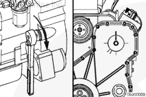
Remove the fuel pump drive gear cover.

Locate top dead center for cylinder number 1 by barring the engine slowly until the line on the pump gear lines up with the line on the gear cover.

SMALL | MEDIUM | LARGE


Remove the rate shape tube assembly. Refer to Procedure 005-090.

Remove the air bleed line. Refer to Procedure 006-056.

SMALL | MEDIUM | LARGE


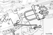
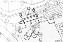
Remove the fuel pump upper support bracket.

SMALL | MEDIUM | LARGE


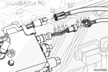
Disconnect the 4-pin Deutsch connector for the pumping control valves.

Disconnect the pressure and temperature sensors.

NOTE: The pressure sensor connector has a potted pigtail connector. This sensor can only be disconnected at the engine harness end of the pigtail harness.

SMALL | MEDIUM | LARGE


 WARNING 

The accumulator module weighs 11 kg [25 lb] and is free to move once the capscrews are removed. Do not drop; personal injury can occur.
 CAUTION 

Do not use air tools. The use of air tools will possibly damage the fuel pump.

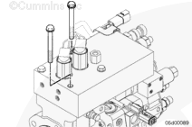
Remove two of the four capscrews that are located diagonally from one another.

SMALL | MEDIUM | LARGE


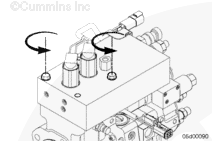
Remove the last two capscrews. Alternately loosen the capscrew to avoid binding. Loosen each capscrew about one turn at a time.

SMALL | MEDIUM | LARGE


 WARNING 

The accumulator module weighs 11 kg [25 lb] and is free to move once the capscrews are removed. Do not drop; personal injury can occur.

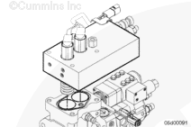
Remove the accumulator module.

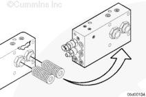
Use as much care as possible to avoid dislodging the springs from the bottom of the accumulator.

SMALL | MEDIUM | LARGE


If the springs are dislodged, the ceramic plungers can fall out. The plungers are matched to each bore.

Reseat the springs fully onto plunger barrels.

Do not interchange the plungers.

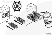
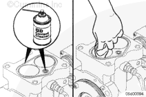
NOTE: Before replacing a ceramic plunger, special care needs to be taken to clean it.

Use QD contact cleaner, Part Number 3824510, to clean the plunger.

SMALL | MEDIUM | LARGE


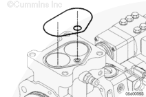
Remove the oil seal ring and fuel passage o-rings.

SMALL | MEDIUM | LARGE
   

Clean and Inspect for Reuse

TOC

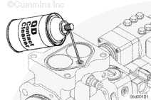
Clean the small fuel passage using the plastic tube provided with the contact cleaner.

Use QD contact cleaner, Part Number 3824510.

SMALL | MEDIUM | LARGE


Clean the o-ring groove and mounting surface on the cam housing and the accumulator.

Make sure the top of the tappets in the cam housing are clean. Wipe out debris with a clean towel.

SMALL | MEDIUM | LARGE


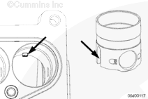
Check the tappets for proper alignment.

The tappets have a slot on the side that engages a pin on the engine side of the cam housing. The pin keeps the roller aligned with the camshaft. Make sure the tappet assembly is properly aligned. Make sure the tappet guide pins and guide pin grooves are not worn excessively.

With the tappets removed, the tappet rollers and camshaft can be inspected. Linear scratches on the cam and rollers is expected; pitting on the nose of the camshaft is not.

SMALL | MEDIUM | LARGE
   

Install

TOC

Install a new oil ring seal and fuel passage o-ring.

Apply Lubriplate™ 105, or equivalent, to the o-ring grooves to hold the o-rings in place.

SMALL | MEDIUM | LARGE


 CAUTION 

The ceramic plungers can fall out when removing the plastic caps or old springs. Do not interchange the plungers. If they fall out, use QD contact cleaner, Part Number 3824510, to clean the plungers thoroughly before replacing them.

If replacing the accumulator module with a new one, remove the springs from the old accumulator module.

Fully install the springs on the plunger barrels of the new accumulator module.

SMALL | MEDIUM | LARGE


NOTE: The use of two 10-mm x 80-mm studs will aid in the installation.

Install the accumulator module.

NOTE: Use care to avoid dislodging the springs on the accumulator and the o-rings on the cam housing.

SMALL | MEDIUM | LARGE


 CAUTION 

Do not use air tools. The use of air tools will possibly damage the fuel pump.

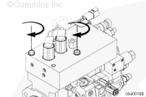
Install two of the four capscrews.

Draw the accumulator module down evenly. Only turn each capscrew about one turn at a time.

Make sure the o-rings are still in their grooves before the accumulator is fully tightened to the cam housing. Use a mirror if necessary.

SMALL | MEDIUM | LARGE


Install remaining two capscrews.

Tighten the four capscrews.

Torque Value:  68  n.m  [50 ft-lb]

SMALL | MEDIUM | LARGE


Install the upper support bracket.

Tighten the capscrews.

Torque Value:  44  n.m  [32 ft-lb]

SMALL | MEDIUM | LARGE
   

Finishing Steps

TOC

Install rate shape tube assembly. Refer to Procedure 005-090.

Install the air bleed line. Refer to Procedure 006-056.

Install the drive gear cover.

Connect the fuel pressure sensor and the fuel temperature sensors to the engine harness.

Connect the pumping control valve connector to the engine harness.

Start the engine and check for fuel leaks or active fault codes.

Road-test the vehicle.

Recheck for fuel leaks or active fault codes.

 
SMALL | MEDIUM | LARGE
Last Modified:  17-Jun-2003