ISC, ISCe, QSC8.3, ISL, ISLe3, ISLe4 and QSL9 Engines – 005-086   Fuel Pump Distributor and Injection Control Valve Module

View Related Topic


Preparatory Steps

TOC

 WARNING 

When using a steam cleaner, wear safety glasses or a face shield, as well as protective clothing. Hot steam can cause personal injury.
 WARNING 

Wear appropriate eye and face protection when using compressed air. Flying debris and dirt can cause personal injury.
 CAUTION 

Fault codes can occur if steam sprays directly on the electrical connections on top of the accumulator block.
  • Thoroughly steam clean the entire fuel pump.
  • Dry the fuel pump with compressed air.
  • Remove the air bleed line. Refer to Procedure
    006-056.
  • Remove the fuel pump from the engine, if necessary. Refer to Procedure
    005-016.
  • Mount the fuel pump in the vise ring if removed. Orient the pump with the distributor facing upward to aid in disassembly.
  • Remove the rate shape tube assembly. Refer to Procedure
    005-090.

SMALL | MEDIUM | LARGE

Remove

TOC

 CAUTION 

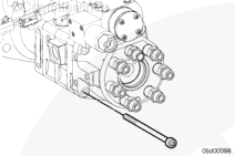
The capscrews also fasten the gear pump module. The gear pump is free to move after the capscrews are removed.

Loosen, but do
not remove, the distributor plug.

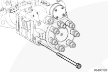
Remove the four mounting capscrews on the distributor.

SMALL | MEDIUM | LARGE


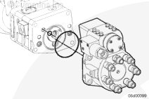
Remove the injection control valve/distributor module.

Remove the drive coupling.

Discard the two o-rings.

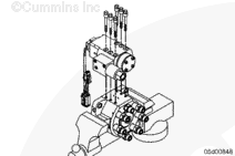
Place the injection control valve/distributor module in a clean bench vise.

SMALL | MEDIUM | LARGE


Remove the injection control valve from the distributor module and install the injection control valve on the new distributor module. Refer to Procedure
005-078.

NOTE: Injection control valves built before January, 2001 are
not reusable. If removing an injection control valve built before January, 2001, use the appropriate injection control valve kit to complete the repair.

SMALL | MEDIUM | LARGE
   

Clean and Inspect for Reuse

TOC

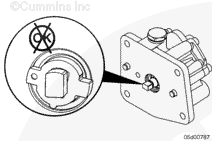
Inspect coupling and gear pump shaft ends for excessive wear. Wear could be found on the inside corners of the coupling groove; such wear, however, is
not common.

A polished surface is acceptable.

SMALL | MEDIUM | LARGE


 CAUTION 

A distributor rotor seizure can cause damage to the gear pump.

If rotor seizure is suspected, inspect the gear pump. Refer to Procedure
005-089.

Replace the gear pump module if wear is visible.

Replace the gear pump module if the gear pump driveshaft is damaged.

SMALL | MEDIUM | LARGE
   

Install

TOC

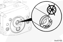
Install the drive coupling.

Center the coupling on the gear pump shaft.

Apply Lubriplate™ 105, or equivalent, to the coupling to keep it from sliding in the shaft groove during assembly.

SMALL | MEDIUM | LARGE


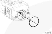
Install new o-rings.

Apply Lubriplate™ 105, or equivalent, to the o-rings to keep them from falling out during assembly.

SMALL | MEDIUM | LARGE


NOTE: This step is
not necessary if you replace the distributor without removing the fuel pump from the engine.

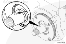
The dowel pin
must be facing up toward the top of the pump.

If the shaft needs to be rotated, install the fuel pump drive nut onto the shaft to provide a means for rotating the shaft.

SMALL | MEDIUM | LARGE


 CAUTION 

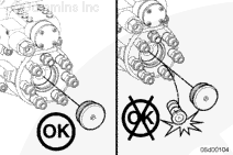
The rotor can slide out once the distributor plug is removed.
 CAUTION 

Do not drop the rotor. Damaging the rotor will necessitate replacement of the entire distributor module.

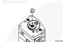
Remove the large plug from the end of the distributor.

Do
not remove the rotor.

SMALL | MEDIUM | LARGE


Install the distributor module.

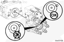
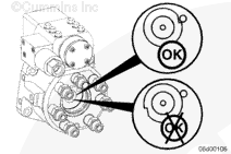
Lightly rotate the rotor with finger pressure until it drops into the slot in the drive coupling.

When properly engaged, the notch in the rotor will align with the hole in the distributor (when the engine is at top dead center for number 1 cylinder).

SMALL | MEDIUM | LARGE


Do
not pinch the o-rings.

Install the four distributor capscrews.

Tighten the capscrews.

Torque Value:  48  n.m  [35 ft-lb]

SMALL | MEDIUM | LARGE


 CAUTION 

The rotor must be properly timed to the fuel pump camshaft. Improper assembly will cause the rotor to be 180 degrees out of time.

If
not properly timed, install the drive coupling and rotor again. Refer to Procedure
005-072.

SMALL | MEDIUM | LARGE


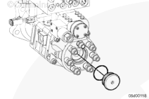
Install a new o-ring on the distributor plug.

Install the large plug at the end of the distributor.

Tighten the distributor plug.

Torque Value:  14  n.m  [120 in-lb]

SMALL | MEDIUM | LARGE
   

Finishing Steps

TOC

  • Install the rate shape tube assembly. Refer to Procedure
    005-090.
  • Install the fuel pump on the engine, if removed. Refer to Procedure
    005-016.
  • Install the air bleed line. Refer to Procedure
    006-056.
  • Use INSITE™ electronic service tool to run the injection control valve click test. Refer to Procedure
    005-078.
  • Start the engine and check for fuel leaks or active fault codes.
  • Road-test the vehicle for at least 1 mile. Check for fuel leaks or active fault codes.

SMALL | MEDIUM | LARGE
Last Modified:  27-Nov-2006