Initial Check
TOC
Measure the outlet pressure at the diagnostic fitting on the CAPS pump at a rated flow condition and compare to the following chart.
Engine Speed (rpm)
Gear Pump Pressure kPa [psi]
200
14 [2]
700
138 [20]
1300
379 [55]
2200
827 [120]
Preparatory Steps
TOC
WARNING
When using a steam cleaner, wear safety glasses or a face shield, as well as protective clothing. Hot steam can cause serious personal injury.
WARNING
Wear appropriate eye and face protection when using compressed air. Flying debris or dirt can cause personal injury.
CAUTION
Make sure that steam does not spray directly on the electrical connections on the top of the accumulator block, or fault codes will possibly occur.
Thoroughly steam-clean the entire fuel pump.
Dry the fuel pump with compressed air.
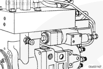
Remove the air bleed line. Refer to Procedure 006-056 .
Remove the fuel pump from the engine. Refer to Procedure 005-016 .
Mount the fuel pump in a vise ring. Orient the pump with the distributor facing upward to aid in disassembly.
Remove the rate shape tube. Refer to Procedure 005-090 .
Remove the distributor module. Refer to Procedure 005-086 .
Clean and Inspect for Reuse
TOC
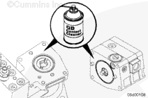
Clean the mounting surfaces of the gear pump and cam housing.
Use QD contact cleaner, Part Number 3824510.
Inspect the drive coupling and shaft ends for excessive wear.
A polished surface is acceptable.
Replace the coupling if wear is visible.
Install
TOC
CAUTION
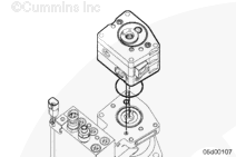
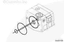
The larger o-rings on either end of the gear pump differ in size. The longer o-ring goes to the side facing the cam housing.
Install new o-rings.
Apply Lubriplate™ 105, or equivalent, to the o-rings to keep them from falling out during assembly.
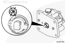
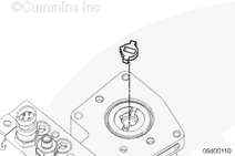
Install the drive coupling.
Center the coupling in the shaft.
Align the gear pump shaft with drive the coupling and install the gear pump module.
Make sure the o-rings are not pinched.
Make sure the timing dowel pin is facing toward the top of the fuel pump.
Finishing Steps
TOC
Install the distributor module. Refer to Procedure 005-086 .
Install the rate shape tube. Refer to Procedure 005-090 .
Install the fuel pump on the engine. Refer to Procedure 005-016 .
Install the air bleed line. Refer to Procedure 006-056 .
Start the engine and check for fuel leaks or active fault codes.
Road-test the vehicle for at least one mile. Recheck for fuel leaks or active fault codes.
Last Modified: 04-Aug-2005
Published by Jack
Hello, I'm Jack, a diesel engine fan and a blogger. I write about how to fix and improve diesel engines, from cars to trucks to generators. I also review the newest models and innovations in the diesel market. If you are interested in learning more about diesel engines, check out my blog and leave your feedback.
View all posts by Jack

 WARNING
  CAUTION





;)
;)
;)
;)
;)
;)
;)
;)
;)
;)
;)
;)
;)
;)
