ISC, ISCe, QSC8.3, ISL, ISLe3, ISLe4 and QSL9 Engines – 005-088   Fuel Pump Cam Housing Module

Preparatory Steps

TOC

 WARNING 

When using a steam cleaner, wear safety glasses or a face shield, as well as protective clothing. Hot steam can cause personal injury.
 WARNING 

Wear appropriate eye and face protection when using compressed air. Flying debris and dirt can cause personal injury.
 CAUTION 

Make sure that steam does not spray directly on the electrical connections on the top of the accumulator block, or fault codes will possibly occur.

Thoroughly steam-clean the entire fuel pump.

Dry the pump with compressed air.

Bar the engine to TDC.

 
SMALL | MEDIUM | LARGE

Remove

TOC

CAPS Fuel System


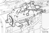
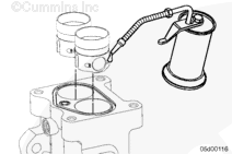
Remove the air bleed line (1). Refer to Procedure 006-056.

Remove the fuel pump from the engine. Refer to Procedure 005-016.

Mount the fuel pump to the mounting plate, Part Number 3162897, and orient the fuel pump with the distributor facing upward to aid in disassembly.

Remove the rate shape tube assembly. Refer to Procedure 005-090.

Remove the accumulator module. Refer to Procedure 005-085.

Remove the distributor module. Refer to Procedure 005-086.

Remove the gear pump module. Refer to Procedure 005-089.

SMALL | MEDIUM | LARGE
   

Clean and Inspect for Reuse

TOC

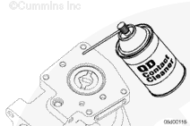
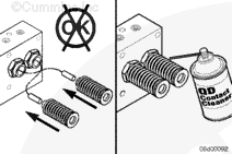
Clean the mounting surfaces of the cam housing.

Use QD contact cleaner, Part Number 3824510.

Inspect the camshaft coupling interface for wear. If the camshaft is worn excessively, replace the cam housing module.

SMALL | MEDIUM | LARGE


 CAUTION 

If the tappets are removed, be sure to install them in the same bore they were removed from.

Remove the roller tappets from the cam housing bores.

Inspect the roller surfaces for pitting and wear.

Make sure the roller rotates freely and smoothly.

Replace the cam housing module if the rollers are worn.

NOTE: It is normal to see lines (scratches) worn in the direction of roller travel. The cam housing or tappets should be replaced if the rollers are pitted.

Examine the tappets guide pin slots. If the guide pin slot is worn more than 25-percent of its original width, the tappet must
be replaced.

SMALL | MEDIUM | LARGE


Inspect the guide pins. If the guide pins are worn or if oil leaks at the cam housing guide pin press fit, the cam housing must be replaced.

Inspect the camshaft lobes for pitting and wear. Replace the cam housing if there is any pitting or wear.

Inspect for raised burrs in the tappet bore. Replace the cam housing if raised burrs are present. Scratching or polishing is normal.

SMALL | MEDIUM | LARGE


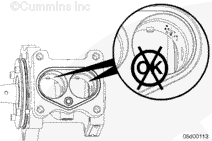
Inspect the tappet bores for scuffing or wear leading into the housing.

Polishing will occur in vertical bands at many places around the inside of the bores.

Polish in the bores is acceptable.

Replace the cam housing if there is severe tappet guide pin wear (more than 25-percent of tappet pin is worn).

SMALL | MEDIUM | LARGE


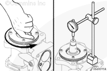
Using fingers, make sure the camshaft turns freely. The bearings must turn smoothly and freely during rotation.

Replace the cam housing if the bearings are tight or rough.

Check the camshaft for end-play.

Camshaft End-Play
mm in
0.05 MAX 0.002

SMALL | MEDIUM | LARGE


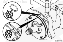
Inspect the oil feed and pump mounting o-ring.

 
SMALL | MEDIUM | LARGE
   

Install

TOC

CAPS Fuel System


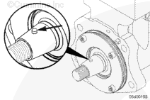
Make sure the timing dowel pin in the camshaft points toward the top of the fuel pump.

 
SMALL | MEDIUM | LARGE


Lubricate the tappets and camshaft lobes with clean 15W-40 engine oil.

Install the roller tappets into the cam housing. Be sure that the tappets guide grooves are oriented correctly onto the tappet guide pins. Also, be sure that the tappet assemblies are installed in their original bores.

Check the tappets for proper alignment.

The tappets have a slot on the side that engages a pin on the engine side of the cam housing. The pin keeps the roller aligned with the camshaft. Make sure the tappet is properly aligned.

SMALL | MEDIUM | LARGE


 CAUTION 

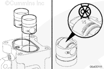
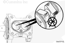
The ceramic plungers will possibly fall out when removing the springs. Do not interchange the plungers or change their upwards orientation. If the plungers are removed, use QD contact cleaner, Part Number 3824510, to clean them before replacing.

NOTE: When assembling the fuel injection pump, take care to keep the ceramic pumping plungers in their original orientation in the accumulator module.

If not already done, install the spring and tappet retainers onto the accumulator or fuel pump barrel assemblies.

SMALL | MEDIUM | LARGE


Install the gear pump module. Refer to Procedure 005-089.

Install the distributor module. Refer to Procedure 005-086.

Install the accumulator module. Refer to Procedure 005-085.

Install the rate shape tube assembly. Refer to Procedure 005-090.

Install the fuel pump onto the engine. Refer to Procedure 005-016.

Install the air bleed line. Refer to Procedure 005-056.

SMALL | MEDIUM | LARGE
   

Finishing Steps

TOC

Start the engine and check for fuel leaks or active fault codes.

Perform repeat throttle snaps to create increased accumulator or fuel rail pressure.

 
SMALL | MEDIUM | LARGE
Last Modified:  04-Aug-2005