When using solvents, acids, or alkaline materials for cleaning, follow the manufacturers recommendations for use. Wear goggles and protective clothing to reduce the possibility of personal injury.
WARNING
Some solvents are flammable and toxic. Read the manufacturer’s instructions before using.
WARNING
Wear appropriate eye and face protection when using compressed air. Flying debris and dirt can cause personal injury.
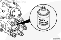
Steam clean the fuel injection pump and the engine in the vicinity of the fuel pump.
Dry with compressed air. Pay special attention to the distributor area.
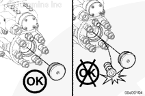
The rotor can slide out during the removal of the distributor plug. If the rotor is dropped, the entire distributor module must be replaced. Do not attempt to start the engine with the distributor plug removed. Doing so can cause the rotor to be ejected from the distributor, causing damage to the rotor.
ISL Only: Remove the air bleed line. Refer to Procedure 006-056.
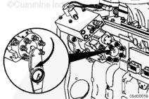
Remove the distributor plug, being sure the rotor does not
fall out.
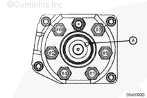
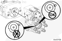
Check the position of the notch on the rotor. It must line up with the alignment mark (A) on the outside of the distributor (when the engine is barred to TDC for the number 1 cylinder). If the alignment is correct, the rotor is properly timed to the engine.
If a mechanical problem exists, indicated by misalignment of the rotor, the entire fuel pump will have to be replaced; refer to Procedure 005-016.
The rotor must be properly timed to the fuel pump camshaft. Improper assembly will cause the rotor to be 180 degrees out of time.
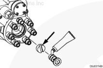
Insert the rotor and coupling into the distributor module completely.
Lightly rotate the rotor with finger-pressure until it drops into the slot in the drive coupling.
When properly engaged, the notch in the rotor will align with the hole in the distributor while the engine is at Number cylinder TDC.
If the rotor will not engage, remove the rotor and drive coupling and try again. Do not tighten the rotor cap if the coupling will not engage.
If not properly timed, remove the rotor and drive coupling and repeat the previous step. Make sure the fuel pump camshaft dowel pin is pointing toward the top of the fuel pump before installing.
Hello, I'm Jack, a diesel engine fan and a blogger. I write about how to fix and improve diesel engines, from cars to trucks to generators. I also review the newest models and innovations in the diesel market. If you are interested in learning more about diesel engines, check out my blog and leave your feedback.
View all posts by Jack
 WARNING
 CAUTION







;)
;)
;)
;)
;)
;)
;)
;)
;)
;)
;)
;)
;)
;)