View Related Topic
Preparatory Steps
TOC
WARNING
When using a steam cleaner, wear safety glasses or a face shield, as well as protective clothing. Hot steam can cause serious personal injury.
WARNING
Wear appropriate eye and face protection when using compressed air. Flying debris and dirt can cause personal injury.
CAUTION
Fault codes can occur if steam sprays directly on the electrical connections on top of the accumulator block.
Thoroughly steam-clean the entire fuel pump.
Dry the fuel pump with compressed air.
Remove the fuel injection pump accumulator. Refer to Procedure 005-085 .
Remove
TOC
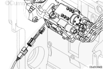
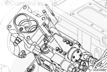
Remove the injection control valve drain line.
Remove the six injection control valve mounting screws.
Remove the injection control valve from the distributor module.
Do not misplace parts during disassembly.
Secure the six bolts, sealing plate, and both crush tubes into a parts bag. The parts are to be returned with the core.
Clean and Inspect for Reuse
TOC
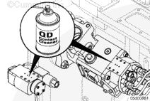
Clean the mounting surface of the distributor module and injection control valve.
Use QD contact cleaner, Part Number 3824510.
Spray or wipe debris away from the three distributor module drillings. Do not allow debris to enter the distributor module drillings.
Inspect the distributor module sealing face for cracks, indentations, and damage.
Replace the distributor module if damage is found.
Install
TOC
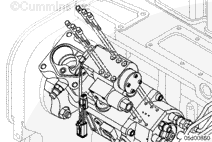
Install guide pins, Part Number 3165166, in the upper left and lower right corner of the distributor module.
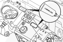
Install the o-rings into the sealing plate using Lubriplate™ to hold them in place.
Slide the sealing plate down over the guide pins.
The o-rings must be securely seated in the sealing plate before proceeding.
Insert crush tubes into the sealing plate.
Check the position of the crush tubes. They must sit flush on the distributor module and must not be installed at an angle.
Install the injection control valve on top of the distributor module using guide pins.
Check that the o-rings are still in their grooves.
Install four bolts through the injection control valve and tighten finger tight.
Remove the two guide pins.
Install the two remaining bolts, finger tight, through the injection control valve.
CAUTION
Bolts must be torqued as described or the injection control valve/distributor module will not function properly. Use a high-quality, calibrated torque wrench.
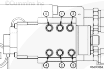
Torque bolts in sequence for each step. Refer to the accompanying illustration for the torque sequence.
Torque Value: Step 1
1.8 n.m [16 in-lb]
Step 2
3.6 n.m [32 in-lb]
Step 3
5.6 n.m [50 in-lb]
Step 4
Torque to 5.6 N•m [50 in-lb] three more times following the torque sequence
Install the injection control valve drain line.
Click Test
TOC
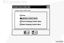
Select Injection Control Valve to initiate the test.
A click will be heard until None is selected on the Control Valve Click Test screen.
If no click is heard, troubleshoot any active fault codes.
The click test will need to be performed after any repairs are made to clear the fault codes.
Last Modified: 08-Oct-2003
Published by Jack
Hello, I'm Jack, a diesel engine fan and a blogger. I write about how to fix and improve diesel engines, from cars to trucks to generators. I also review the newest models and innovations in the diesel market. If you are interested in learning more about diesel engines, check out my blog and leave your feedback.
View all posts by Jack
 WARNING
  CAUTION


;)
;)
;)
;)
;)
;)
;)
;)
;)
;)
;)
;)
;)
;)
;)
;)
;)
;)