General Information
|
TOC |
|
|
|
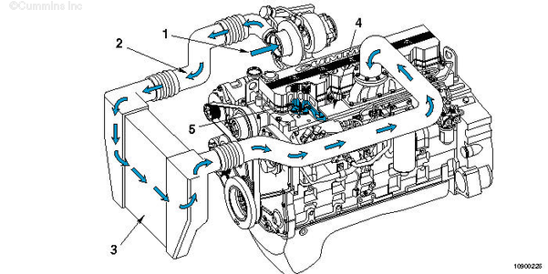
| Charge Air Cooled Engines |
- Intake Air Inlet to Turbocharger
- Turbocharger Air to Charge Air Cooler
- Charge Air Cooler
- Intake Manifold (integral part of cylinder head)
- Intake Valve.
|
|
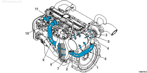
| QSC8.3 and QSL9 Marine Aftercooled Engines |
NOTE: The graphic above is the QSL9 engine configuration. The aftercooler on the QSC8.3 engine mounts to the engine differently, but the air flow from the air inlet to the combustion chamber is the same.
- Air inlet to air filter
- Air filter assembly
- Intake air restriction indicator
- Air inlet to turbocharger compressor
- Turbocharger compressor discharge
- Air discharge from turbocharger compressor to aftercooler inlet
- Aftercooler air inlet
- Aftercooler
- Air discharge from aftercooler to intake manifold
- Air manifold
- Intake valve.
|
Last Modified: 26-Feb-2009
Published by Jack
Hello, I'm Jack, a diesel engine fan and a blogger. I write about how to fix and improve diesel engines, from cars to trucks to generators. I also review the newest models and innovations in the diesel market. If you are interested in learning more about diesel engines, check out my blog and leave your feedback.
View all posts by Jack
;)
;)
;)
;)